X
General-purpose Basic Switch
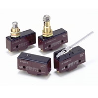
Direct Current Switch with Built-in Magnetic Blowout
Related Contents
last update: December 18, 2015
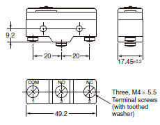
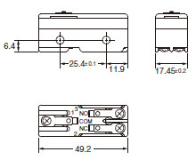
(Unit: mm)
Terminals
Screw Terminals (-B)
Solder Terminal (-A)
("-A" is not included in the model numbers.)
Note: 1. Tighten the terminal screws to a torque of 0.78 to 1.18 Nm.
2. Unless otherwise specified, a tolerance of ±0.4 mm applies to all dimensions.
3. In case of DC voltage, set the COM to the positive terminal.
2. Unless otherwise specified, a tolerance of ±0.4 mm applies to all dimensions.
3. In case of DC voltage, set the COM to the positive terminal.
Mounting
Use M4 mounting screws with plane washers or spring washers to securely mount the Switch. Tighten the screws to a torque of 1.18 to 1.47 Nm.
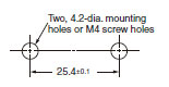
The Switch can be panel mounted, provided that the hexagonal nut of the actuator is tightened to a torque of 2.94 to 4.9 Nm.
The models, illustrations, and graphics are for screw-terminal models. (The dimensions for models that are omitted here are the same as for pin-plunger models.)
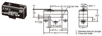
Pin Plunger
X-10G-B
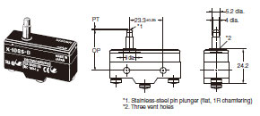
Slim Spring Plunger
X-10GS-B
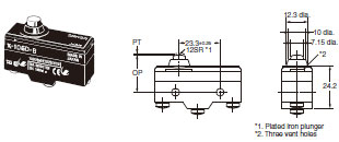
Short Spring Plunger
X-10GD-B
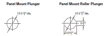
Panel Mount Plunger
X-10GQ-B
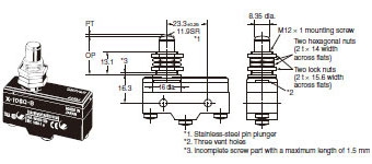
Note: Do not use both the M12 mounting screw and the mounting holes in the case at the same time. Doing so will cause
stress to be applied to the Switch, possibly damaging the case or cover.
stress to be applied to the Switch, possibly damaging the case or cover.
Panel Mount Roller Plunger
X-10GQ22-B
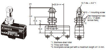
Note: Do not use both the M12 mounting screw and the mounting holes in the case at the same time. Doing so will cause
stress to be applied to the Switch, possibly damaging the case or cover.
stress to be applied to the Switch, possibly damaging the case or cover.
Panel Mount Cross Roller Plunger
X-10GQ21-B
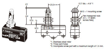
Note: Do not use both the M12 mounting screw and the mounting holes in the case at the same time. Doing so will cause
stress to be applied to the Switch, possibly damaging the case or cover.
stress to be applied to the Switch, possibly damaging the case or cover.
Leaf Spring
X-10GL-B
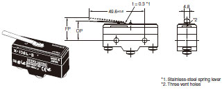
Note: Unless otherwise specified, a tolerance of ±0.4 mm applies to all dimensions.

* Be sure to use the switch at the rated OT value of 1.6 mm.
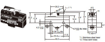
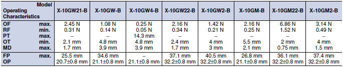
Short Hinge Lever
X-10GW21-B
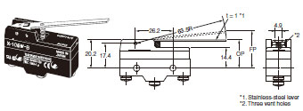
Hinge Lever
X-10GW-B
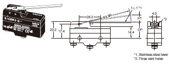
Low-force Hinge Lever
X-10GW4-B
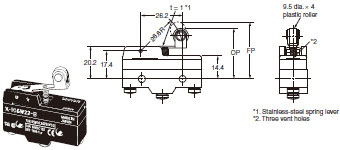
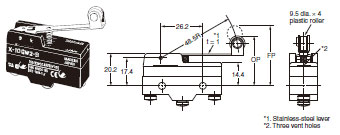
Short Hinge Roller Lever
X-10GW22-B
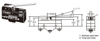
Hinge Roller Lever
X-10GW2-B
Reverse Hinge Lever
X-10GM-B
Reverse Short Hinge Lever
X-10GM22-B
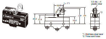
Reverse Hinge Roller Lever
X-10GM2-B
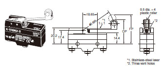
Note: Unless otherwise specified, a tolerance of ±0.4 mm applies to all dimensions.
Terminal Covers
AP-A
Soldering Terminal Use (Phenol Resin)
Note: The Cover has five thin, easy-to-separate portions for easy lead wire connections.
AP-B
Screw Terminal Use (Phenol Resin)
Note: The Cover has six thin, easy-to-separate portions for easy lead wire connections.
AP1-A
Soldering Terminal Use (Metal Press Mold)
Note: The Cover has five holes for easy lead wire connections.
AP1-B
Screw Terminal Use (Metal Press Mold)
Note: The Cover has six holes for easy lead wire connections.
AP-Z
Soldering or Screw Terminal Use (Vinyl Chloride)
Note: Each dimension has a tolerance of ±0.4 mm unless otherwise specified. (±0.8 mm for the AP-Z)
Separator
SEPARATOR FOR Z
Note: 1. Each dimension has a tolerance of ±0.4 mm unless otherwise specified.
2. The material is EAVTC (Epoxide Alkyd Varnished Tetron Cloth) and its heat-resisting temperature is 130°C.
Actuators
Hinge Lever
XAA-1
Hinge Roller Lever
ZAA-2
Short Panel Mount Plunger
ZAQ-3
Medium Panel Mount Plunger
ZAQ-2
Long Panel Mount Plunger
ZAQ-1
Panel Mount Roller Plunger
ZAQ-22
Note: Each dimension has a tolerance of ±0.4 mm unless otherwise specified.
last update: December 18, 2015