CS1W-DA
SYSMAC CS-series Analog I/O Unit
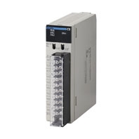
For Various Analog I/Os
Related Contents
- Features
- Lineup
- Specifications
- Dimensions
- Catalog / Manual / CAD / Software
last update: October 9, 2013
| Item | CS1W-DA041 | CS1W-DA08V | CS1W-DA08C | |
|---|---|---|---|---|
| Applicable PLC model | CS series | |||
| Unit type | CS1 Special I/O Unit | |||
| Isolation *1 | Between I/O and PLC signals: Photocoupler (No isolation between individual I/O signals.) |
|||
| External terminals | 21-point detachable terminal block (M3 screws) | |||
| Power consumption | 130 mA max. at 5 VDC, 180 mA max. at 26 VDC |
130 mA max. at 5 VDC, 180 mA max. at 26 VDC |
130 mA max. at 5 VDC, 250 mA max. at 26 VDC |
|
| Dimensions (mm) *2 | 35 × 130 × 126 (W × H × D) | |||
| Weight | 450 g max. | |||
| General specifications | Conforms to general specifications for SYSMAC CS-series Series. | |||
| Mounting position | CS-series CPU Rack or CS-series Expansion Rack (Cannot be mounted to a C200H Expansion I/O Rack or a SYSMAC BUS Slave Rack.) |
|||
| Maximum number of Units | Depends on the Power Supply Unit. *3 | |||
| Data exchange with CPU Units *4 | Special I/O Unit Area CIO 200000 to CIO 295915 (Words CIO 2000 to CIO 2959) |
|||
| Internal Special I/O Unit DM Area (D20000 to D29599) | ||||
|
Output specifications |
Number of analog outputs | 4 | 8 | 8 |
| Output signal ranges *5 | 1 to 5 V/4 to 20 mA 0 to 5 V 0 to 10 V - 10 to 10V |
1 to 5 V 0 to 5 V 0 to 10 V - 10 to 10 V |
4 to 20 mA | |
| Output impedance | 0.5 Ω max. (for voltage output) | |||
|
Max. output current (for 1 point) |
12 mA (for voltage output) | |||
|
Maximum permissible load resistance |
600 Ω (current output) *9 | --- | 600 Ω (current output) *8 | |
| Resolution | 4,000 (full scale) | |||
| Set data | 16-bit binary data | |||
| Accuracy *6 | 23 ± 2 ° C: Voltage output: ± 0.3% of full scale Current output: ± 0.5% of full scale |
|||
| 0 ° C to 55 ° C: Voltage output: ± 0.5% of full scale Current output: ± 0.8% of full scale |
||||
| D/A conversion time *7 | 1.0 ms/point max. | |||
|
Output functions |
Output hold function | Outputs the specified output status (CLR, HOLD, or MAX) under any of the following circumstances. When the Conversion Enable Bit is OFF. *8 In adjustment mode, when a value other than the output number is output during adjustment. When there is an output setting error or a fatal error occurs at the PLC. When the CPU Unit is on standby. When the Load is OFF. |
||
*1. Do not apply a voltage higher than 600 V to the terminal block when performing withstand voltage test on this Unit.
*2. Refer to Dimensions for details on the Unit's dimensions.
*3. Maximum Number of Units
| Power Supply Unit | CS1W-DA041/08V | CS1W-DA08C |
|---|---|---|
| C200HW-PA204
C200HW-PA204S C200HW-PA204R C200HW-PD024 |
3 Units max. | 2 Units max. |
| C200HW-PA209R | 7 Units max. | 5 Units max. |
The maximum number of Units that can be mounted to one Rack varies depending on the current consumption of
the other Units mounted to the Rack and may be less than the number shown in the above table.
*4. Data Exchange with CPU Units
the other Units mounted to the Rack and may be less than the number shown in the above table.
*4. Data Exchange with CPU Units
|
Special I/O Unit Area CIO 200000 to CIO 295915 (Words CIO 2000 to CIO 2959) |
Exchanges 10 words of data per Unit. | CPU Unit to Analog Output Unit |
Analog output setting data Conversion Enable Bit |
|---|---|---|---|
| Analog Output Unit to CPU Unit |
Alarm flags | ||
|
Internal Special I/O Unit DM Area (D20000 to D29599) |
Transmits 100 words of data per Unit at power-up or when the Unit is restarted. |
CPU Unit to Analog Output Unit |
Output signal conversion enable/disable, output signal range setting Output status for output hold |
*5. Output signal ranges can be set for each output.
*6. The accuracy is given for full scale. For example, an accuracy of ±0.3% means a maximum error of ±12 (BCD).
*7. D/A conversion time is the time required for converting and outputting the PLC data. It takes at least one cycle for
the data stored in the PLC to be read by the Analog Output Unit.
*8. When the operation mode for the CPU Unit is changed from RUN mode or MONITOR mode to PROGRAM mode, or
when the power is turned ON, the Output Conversion Enable Bit will turn OFF. The output status specified according
to the output hold function will be output.
*9. The load resistance is adjusted to 250 Ω at the factory. Always adjust the offset gain before application when the load
resistance is not 250 Ω.
The CS1W-DA041 is adjusted for current outputs (load resistance: 250 Ω) at the factory. Adjust the offset gain before
application when using voltage outputs.
last update: October 9, 2013