Discontinued On Mar. 2017
H8GN
Preset Counter/Timer (48 × 24)
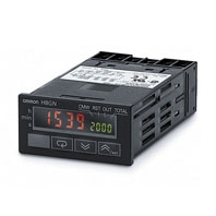
A DIN 48 × 24 Preset Counter. Compact, Yet Equipped with Communication.
* Information in this page is a reference that you created on the basis of information in the product catalog before the end of production, may be different from the current situation, such as goods for / supported standards options / price / features of the product. Before using, please check the compatibility and safety system.
Related Contents
- Features
- Lineup
- Specifications
- Dimensions
- Catalog / Manual / CAD / Software
last update: August 3, 2015
Ratings
| Rated supply voltage | 24 VDC | |
|---|---|---|
| Operating voltage range | 85% to 110% of rated supply voltage | |
| Power consumption | 1.5 W max. (for max. DC load) (Inrush current: 15 A max.) | |
| Mounting method | Flush mounting | |
| External connections | Screw terminals (M3 screws) | |
| Terminal screw tightening
torque |
0.5 Nm max. | |
| Attachment | Waterproof packing, flush mounting bracket | |
| Display | 7-segment, negative transmissive LCD; time display (h, min, s); CMW, OUT, RST, TOTAL
Present value (red, 7-mm-high characters); Set value (green, 3.4-mm-high characters) |
|
| Digits | PV: 4 digits
SV: 4 digits When total count value is displayed: 8 digits (Zeros suppressed) |
|
| Memory backup | EEPROM (non-volatile memory) (number of writes: 100,000 times) | |
| Counter | Maximum
counting speed |
30 Hz or 5 kHz * |
| Counting range | -999 to 9,999 | |
| Input modes | Increment, decrement, individual, quadrature inputs | |
| Output modes | N, F, C, or K | |
| Timer | Time ranges | 0.000 to 9.999 s, 0.00 to 99.99 s, 0.0 to 999.9 s, 0 to 9999 s, 0 min 00 s to 99 min
59 s, 0.0 to 999.9 min, 0 h 00 min to 99 h 59 min, 0.0 h to 999.9 h, 0 h to 9999 h |
| Timer modes | Elapsed time (Up), remaining time (Down) | |
| Output modes | A, B, D, E, F, or Z | |
| Inputs | Input signals | For Counter: CP1, CP2, and reset
For Timer: Start, gate, and reset |
| Input method | No-voltage input (contact short-circuit and open input)
Short-circuit (ON) impedance: 1 kΩ max. (Approx. 2 mA runoff current at 0 Ω) Short-circuit (ON) residual voltage: 2 VDC max. Open (OFF) impedance: 100 kΩ min. Applied voltage: 30 VDC max. |
|
| Start, reset, gate | Minimum input signal width: 1 or 20 ms (selectable) | |
| Power reset | Minimum power-opening time: 0.5 s | |
| Control output | SPDT contact output: 3 A at 250 VAC/30 VDC, resistive load (cosφ = 1) | |
| Minimum applied load | 10 mA at 5 VDC (failure level: P, reference value) | |
| Reset system | External, manual, and power supply resets (for timer in A, B, D, E, or Z modes) | |
| Sensor waiting time | 260 ms max. (Inputs cannot be received during sensor wait time if control outputs are
turned OFF.) |
|
* The figures given for maximum counting speed are for incrementing or decrementing operation with a prescale value
of ×1. If prescaling is used and 5 kHz is set, the maximum counting speed will be reduced to about half. The maximum
counting speed will also be reduced to about half when the up/down mode is selected.
of ×1. If prescaling is used and 5 kHz is set, the maximum counting speed will be reduced to about half. The maximum
counting speed will also be reduced to about half when the up/down mode is selected.
Characteristics
| Timer
function |
Accuracy of operating
time and setting error (including temperature and voltage effects) |
Signal start: ± 0.03% ± 30 ms max.
Power-ON start: ± 0.03% ± 50 ms max. |
|---|---|---|
| Insulation resistance | 100 MΩ min. (at 500 VDC) | |
| Dielectric strength | 1,500 VAC, 50/60 Hz for 1 min between output terminals and non-current-
carrying metal parts 510 VAC, 50/60 Hz for 1 min between current-carrying terminals (except output terminals) and non-current-carrying metal parts 1,500 VAC, 50/60 Hz for 1 min between output terminals and current-carrying terminals (except output terminals) 500 VAC, 50/60 Hz for 1 min between communications terminals and current- carrying terminals (except output terminals) 1,000 VAC, 50/60 Hz for 1 min between contacts not located next to each other |
|
| Noise immunity | Square-wave noise by noise simulator;
±480 V (between power terminals), ± 600 V (between input terminals) |
|
| Static immunity | ± 8 kV (malfunction), ± 15 kV (destruction) | |
| Vibration
resistance |
Malfunction | 10 to 55 Hz with 0.35-mm single amplitude each in three directions for 10 min |
| Destruction | 10 to 55 Hz with 0.75-mm single amplitude each in three directions for 2 h | |
| Shock
resistance |
Malfunction | 100 m/s2, 3 times each in six directions |
| Destruction | 300 m/s2, 3 times each in six directions | |
| Life
expectancy |
Mechanical | 10 million operations |
| Electrical | 100,000 operations min. (3 A at 250 VAC, resistive load) *1 | |
| Ambient
temperature |
Operating | -10°C to 55°C (with no icing or condensation) |
| Storage | -25°C to 65°C (with no icing or condensation) | |
| Ambient humidity | 25% to 85% | |
| EMC | (EMI): EN61326-1 *2
Emission Enclosure: EN55011 Group 1 Class A (EMS): EN61326-1 *2 Immunity ESD: EN61000-4-2: 4 kV contact discharge (level 2); 8 kV air discharge (level 3) Immunity RF-interference: EN61000-4-3: 10 V/m (Amplitude-modulated, 80 MHz to 1 GHz) (level 3); 10 V/m (Pulse-modulated, 900 MHz ± 5 MHz) (level 3) Immunity Conducted Disturbance: EN61000-4-6: 3 V (0.15 to 80 MHz) (level 2) Immunity Burst: EN61000-4-4: 2 kV power-line (level 3); 1 kV I/O signal-line (level 4); 1 kV communications-line (level 3) Immunity Surge: EN61000-4-5: 1 kV between lines (power and output lines) (level 3); 2 kV between grounds (power and output lines) (level 3) |
|
| Approved standards | UL508, CSA C22.2 No.14
Conforms to EN61010-1/IEC61010-1 (Pollution degree 2/overvoltage category II) Conforms to VDE0106/P 100 (Finger Protection) |
|
| Case color | Rear section: Gray smoke; Front section: N1.5 (black) | |
| Degree of protection | Panel surface: IP66 and NEMA Type 4X (indoors)
Rear case: IP20 Terminal block: IP20 |
|
| Weight | Approx. 80 g | |
*1. Refer to the Life-test Curve.
*2. Industrial electromagnetic environment (EN/IEC 61326-1 Table 2)
*2. Industrial electromagnetic environment (EN/IEC 61326-1 Table 2)
Communications Specifications
| Transmission path connections | Multidrop |
|---|---|
| Communications method | RS-485 (two-wire, half duplex) |
| Synchronization method | Start-stop synchronization |
| Baud rate * | 1,200/2,400/4,800/9,600 bit/s |
| Transmission code | ASCII |
| Data bit length * | 7 or 8 bits |
| Stop bit length * | 1 or 2 bits |
| Error detection | Vertical parity (none, even, or odd) *
Block check character (BCC) |
| Flow control | Not supported. |
| Interface | RS-485 |
| Retry function | Not supported. |
| Communications buffer | 40 bytes |
| Reading and writing from H8GN | Reading present value and totalizing count value; reading/writing preset and set
values; switching between SV-banks; switching between communications write- enabled/write-prohibited; reading/writing other initial and advanced function setting parameters |
* The baud rate, data bit length, stop bit length, and vertical parity can be individually set using the communications
setting level.
setting level.
last update: August 3, 2015
 Product Category
- Control Components
-
Counters
-
Discontinued
- H8GN
-
Discontinued
-