Discontinued On Mar. 2022
H7CZ
Digital Counter
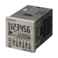
Easy to Use and Easy to Read.
* Information in this page is a reference that you created on the basis of information in the product catalog before the end of production, may be different from the current situation, such as goods for / supported standards options / price / features of the product. Before using, please check the compatibility and safety system.
Related Contents
- Features
- Lineup
- Specifications
- Dimensions
- Catalog / Manual / CAD / Software
last update: August 3, 2015
Ratings
| Models | H7CZ-L8 | H7CZ-L8D1 | |
|---|---|---|---|
| Configuration | 1-stage preset counter | ||
| Ratings | Power supply voltage *1 | 100 to 240 VAC, 50/60 Hz | 24 VAC, 50/60 Hz or 12 to 24 VDC |
| Operating voltage
fluctuation range |
85% to 110% of rated supply voltage (12 to 24 VDC: 90% to 110%) | ||
| Power consumption | Approx. 9.4 VA at 100 to 240 VAC,
Approx. 7.2 VA/4.7 W at 24 VAC/12 to 24 VDC |
||
| Mounting method | Flush mounting or surface mounting | ||
| External connections | 8-pin socket | ||
| Degree of protection | IEC IP66, UL508 Type 4X (indoors) for panel surface only and only when Y92S-
29 Waterproof Packing is used. |
||
| Input signals | Count, Reset | ||
| Counter | Maximum counting speed | 30 Hz or 10 kHz (switchable) (ON/OFF ratio 1:1) | |
| Input mode | Increment, Decrement | ||
| Output mode | N, F, C, R, K-1, P, Q, and A. | ||
| One-shot output time | 0.01 to 99.99 s | ||
| Reset system | External (minimum reset signal width: 1 ms or 20 ms, selectable), Manual, and
Automatic reset (internal according to C, R, P, and Q mode operation) |
||
| Prescaling function | Yes (0.001 to 99.999) | ||
| Decimal point adjustment | Yes (rightmost 3 digits) | ||
| Sensor waiting time | 290 ms max. (Control output is turned OFF and no input is accepted during
sensor waiting time.) |
||
| Input method | No-voltage inputs:
ON impedance: 1 kΩ max. (Leakage current: 12 mA at 0 Ω) ON residual voltage: 3 V max. OFF impedance: 100 kΩ min. |
||
| Control output | 3 A at 250 VAC/30 VDC, resistive load (cosφ=1), Minimum applied load: 10 mA
at 5 VDC (failure level: P, reference value) |
||
| Display *2 | LCD
Character height Count value: 10 mm Set value: 6 mm |
||
| Digits | 6 digits
-99999 to 999999 (-5 digits to +6 digits) |
||
| Memory backup | EEPROM (overwrites: 100,000 times min.) that can store data for 10 years min. | ||
| Operating temperature range | -10 to 55°C (-10 to 50°C if Counters are mounted side by side) (with no
icing or condensation) |
||
| Storage temperature range | -25 to 70°C (with no icing or condensation) | ||
| Operating humidity range | 25% to 85% | ||
| Front panel color | Light gray (5Y7/1) | ||
*1. Do not use the output from an inverter as the power supply.The ripple must be 20% maximum for DC power.
*2. The display is lit only when the power is ON. Nothing is displayed when power is OFF.
Characteristics
| Insulation resistance | 100 MΩ min. (at 500 VDC) between current-carrying terminals and exposed non-
current-carrying metal parts, and between non-continuous contacts |
|
|---|---|---|
| Dielectric strength | 2,000 VAC, 50/60 Hz for 1 min between current-carrying metal parts and non-current-
carrying metal parts 2,000 VAC, 50/60 Hz for 1 min between power supply and input circuit (1,000 VAC for 24 VAC/12 to 24 VDC) 1,000 VAC, 50/60 Hz for 1 min between control output, power supply, and input circuit (2,000 VAC) 1,000 VAC, 50/60 Hz for 1 min between non-continuous contacts |
|
| Impulse withstand voltage | 3.0 kV between power terminals (1.0 kV for models with 24 VAC/12 to 24 VDC)
4.5 kV between current-carrying terminals and exposed non-current-carrying metal parts (1.5 kV for models with 24 VAC/12 to 24 VDC) |
|
| Noise immunity | ±1.5 kV between power terminals
±600 V between input terminals Square-wave noise by noise simulator (pulse width: 100 ns/1 μs, 1-ns rise) |
|
| Static immunity | Malfunction: 8 kV
Destruction: 15 kV |
|
| Vibration
resistance |
Destruction | 10 to 55 Hz with 0.75-mm single amplitude each in three directions for 2 h each |
| Malfunction | 10 to 55 Hz with 0.35-mm single amplitude each in three directions for 10 min each | |
| Shock
resistance |
Destruction | 300 m/s2 each in three directions |
| Malfunction | 100 m/s2 each in three directions | |
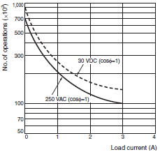
| Life expectancy | Mechanical: 10,000,000 operations min.
Electrical: 100,000 operations min. (3 A at 250 VAC, resistive load, ambient temperature condition: 23°C)* |
|
| Weight | Approx. 100 g (Counter only) | |
* Refer to the Life-test Curve.
Life-test Curve (Reference Values)
Resistive load
Inductive load
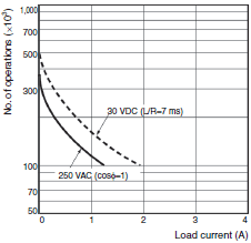
A current of 0.15 A max. can be switched at 125 VDC (cosφ=1) and current of 0.1 A max. can be switched if L/R=7 ms. In both cases, a life of 100,000 operations can be expected.
Applicable Standards
| Approved safety
standards |
cULus (or cURus): UL508/CSA C22.2 No. 14 *1
EN 61010-1 (IEC 61010-1): Pollution degree 2/overvoltage category II B300 PILOT DUTY 1/4 HP 120 VAC, 1/3 HP, 240 VAC, 3 A resistive load VDE0106/P100 (finger protection) |
|---|---|
| EMC | (EMI) EN61326-1 *2
Emission Enclosure: EN 55011 Group 1 class A Emission AC mains: EN 55011 Group 1 class A (EMS) EN61326-1 *2 Immunity ESD: EN 61000-4-2: 4 kV contact discharge; 8 kV air discharge Immunity RF-interference: EN 61000-4-3: 10 V/m (Amplitude-modulated, 80 MHz to 1 GHz); 10 V/m (Pulse-modulated, 900 MHz ±5 MHz) Immunity Conducted Disturbance: EN 61000-4-6: 10 V (0.15 to 80 MHz) Immunity Burst: EN 61000-4-4: 2 kV power-line; 1 kV I/O signal-line Immunity Surge: EN 61000-4-5: 1 kV line to lines (power and output lines); 2 kV line to ground (power and output lines) Immunity Voltage Dip/Interruption: EN 61000-4-11: 0.5 cycle, 100% (rated voltage) |
*1. The following safety standards apply to H7CZ.
cUL (Listing): Applicable when an OMRON P2CF(-E) Socket is used.
cUR (Recognition): Applicable when any other socket is used.
*2. Industrial electromagnetic environment (EN/IEC 61326-1 Table 2)
cUL (Listing): Applicable when an OMRON P2CF(-E) Socket is used.
cUR (Recognition): Applicable when any other socket is used.
*2. Industrial electromagnetic environment (EN/IEC 61326-1 Table 2)
I/O Functions
Using as a Counter *1
| Inputs | Count | • Reads counting signals.
• Increment and decrement inputs accepted. |
|---|---|---|
| Reset | • Resets present value and outputs.*2
• Counting cannot be performed during reset input. • Reset indicator is lit while reset input is ON. |
|
| Outputs | OUT | Outputs signals according to the specified output mode when a set value is reached. |
*1. For information on operation of I/O functions, refer to Catalog.
*2. In elapsed time mode, the present value returns to 0; in remaining time mode, the present value returns to the set
value.
*2. In elapsed time mode, the present value returns to 0; in remaining time mode, the present value returns to the set
value.
The following table shows the delay from when the reset signal is input until the output is turned OFF. (Reference values)
| Minimum reset signal width | Output delay time |
|---|---|
| 1 ms | 0.8 to 1.2 ms |
| 20 ms | 15 to 25 ms |
last update: August 3, 2015
 Product Category
- Control Components
-
Counters
-
Discontinued
- H7CZ
-
Discontinued
-