Discontinued On Mar. 2024
KM1
Multi-circuit Smart Power Monitor
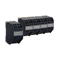
New Ways to Uncover Power Savings. Measure Multiple Distribution Panels at the Same Time.
* Information in this page is a reference that you created on the basis of information in the product catalog before the end of production, may be different from the current situation, such as goods for / supported standards options / price / features of the product. Before using, please check the compatibility and safety system.
Related Contents
- Features
- Lineup
- Specifications
- Dimensions
- Catalog / Manual / CAD / Software
last update: October 1, 2015
Ratings
| Model | Master Unit | Slave Unit | |||
|---|---|---|---|---|---|
| KM1-PMU2A-FLK
(Dual Power Systems) |
KM1-PMU1A-FLK
(Single Power System) |
KM1-EMU8A-FLK
(Pulses/ Temperatures) |
KE1-CTD8E
(CT Extension Unit) |
||
| Applicable phase wiring
method |
Single-phase two-
wire, single-phase threewire, and three-phase three- wire |
Single-phase two-
wire, single-phase three-wire, three- phase three-wire, and three-phase four-wire |
- | Single-phase two-
wire, single-phase three-wire, three- phase three-wire, and three-phase four-wire |
|
| Maximum number of CT
connections |
4 | 3 | - | 8 | |
| Selectable types of CT
capacities |
2 types | 1 type | - | Two types per Slave
Unit |
|
| Power
supply |
Rated power
supply voltage |
100 to 240 VAC, 50/60 Hz | - | ||
| Allowable supply
voltage range |
85% to 110% of rated power supply voltage | - | |||
| Power supply
allowable frequency range |
45 to 65 Hz | - | |||
| Power
consumption |
Standalone: 10 VA max.,
Maximum expansion: 14 VA max. |
10 VA max. | - | ||
| Input | Rated input
voltage |
100 to 480 VAC
(single-phase, 2- wire): Line voltage 100/200 VAC (single-phase, 3- wire): Phase voltage/line voltage 100 to 480 VAC (3-phase, 3-wire): Line voltage |
100 to 480 VAC
(single-phase, 2- wire): Line voltage 100/200 VAC (single-phase, 3-wire): Phase voltage/line voltage 100 to 480 VAC (3-phase, 3-wire): Line voltage 58 to 277 VAC (3-phase, 4-wire): Phase voltage |
- | |
| Rated input
current (CT) |
(5, 50, 100, 200, 400, or 600 A) | - | (5, 50, 100, 200, 400,
or 600 A) |
||
| Rated input
power |
With 5-A CT: 4 kW
With 50-A CT: 40 kW With 100-A CT: 80 kW With 200-A CT: 160 kW With 400-A CT: 320 kW With 600-A CT: 480 kW |
- | |||
| Rated input
frequency |
50/60 Hz | - | |||
| Allowable input
frequency range |
45 to 65 Hz | - | |||
| Allowable input
voltage |
110% of rated input voltage (continuous) | - | |||
| Allowable input
current |
120% of rated input current (continuous) | - | 120% of rated input
current (continuous) |
||
| Rated input load | Voltage input: 0.5 VA max. (excluding power
supply) Current input: 0.5 VA max. (for each input) |
- | Current input: 0.5 VA
max. (for each input) |
||
| Clock | Clock setting | 2012 to 2099 (Adjusted for leap years during this period.) | - | ||
| Clock accuracy | ±1.5 min./month (at 23°C) | - | |||
| Clock backup
period |
Seven-day backup with an electric double-layer capacitor (after
being powered for at least 24 hours and when at 23°C when the power is turned OFF) |
- | |||
| Ambient operating
temperature |
-10 to 55°C (with no condensation or icing) | ||||
| Storage humidity | -25 to 65°C (with no condensation or icing) | ||||
| Ambient operating
humidity |
25% to 85% | ||||
| Storage humidity | 25% to 85% | ||||
| Altitude | 2,000 m max. | ||||
| Installation environment | Overvoltage category II, pollution degree 2, measurement category II | ||||
| Compliant standards | EN/IEC 61010-2-030 and EN/IEC 31626-1 Industrial electromagnetic environment | ||||
Performance
| Model | Master Unit | Slave Unit | |||
|---|---|---|---|---|---|
| KM1-PMU2A-FLK
(Dual Power Systems) |
KM1-PMU1A-FLK
(Single Power System) |
KM1-EMU8A-FLK
(Pulses/ Temperatures) |
KE1-CTD8E
(CT Extension Unit) |
||
| Accu-
racy *1 |
Voltage | ±1.0% FS, ±1 digit; or, ±2.0% FS, ±1 digit
for voltage across Vtr under the same conditions |
- | ||
| Current | ±1.0% FS, ±1 digit
However, the accuracy is ±2.0% FS, ±1 digit for the phase-S current for a three- phase, three-wire circuit and the phase- N current for a singlephase, three-wire circuit under the same conditions. |
- | ±1.0% FS, ±1 digit | ||
| However, the accuracy
is ±2.0% FS, ±1 digit for the phase-S current for a three-phase, three-wire circuit and the phase-N current for a single-phase, three- wire circuit under the same conditions. |
|||||
| Power (active
power and reactive power) |
Active power and reactive power
±2.0% FS, ±1 digit (Power factor = 1) |
- | Active power and
reactive power ±2.0% FS, ±1 digit (Power factor = 1) |
||
| Frequency | ±0.3 Hz ±1 digit | - | |||
| Power factor
*2 |
±5.0% FS at an ambient temperature of
23°C, rated input, rated frequency, and a power factor of 0.5 to 1 to 0.5 |
- | ±5.0% FS at an
ambient temperature of 23°C, rated input, rated frequency, and a power factor of 0.5 to 1 to 0.5 |
||
| Temperature | - | ±5°C two hours
after the power supply is turned ON (after performing any adjustments for the ambient temperature) |
- | ||
| Temperature infl uence | ±1.0% FS (percentage of the
measurement value at an ambient temperature of 23°C, rated input, rated frequency, and a power factor of 1 in the operating temperature range) |
±1.0% FS
(percentage of the measurement value at an ambient temperature of 23°C in the operating temperature range) |
±1.0% FS (percentage
of the measurement value at an ambient temperature of 23°C, rated input, rated frequency, and a power factor of 1 in the operating temperature range) |
||
| Infl uence of frequency | ±1.0% FS (percentage of the
measurement value at an ambient temperature of 23°C, rated input, rated frequency, and a power factor of 1 in the rated frequency ±5 Hz range) |
- | ±1.0% FS (percentage
of the measurement value at an ambient temperature of 23°C, rated input, rated frequency, and a power factor of 1 in the rated frequency ±5 Hz range) |
||
| Infl uence of harmonics | ±0.5% FS (at ambient temperature of
23°C, error for superimposed 2nd, 3rd, 5th, 7th, 9th, 11th, and 13th harmonics for a content percentage of 30% for current and 5% for voltage of the basic wave) |
- | ±0.5% FS (at ambient
temperature of 23°C, error for superimposed 2nd, 3rd, 5th, 7th, 9th, 11th, and 13th harmonics for a content percentage of 30% for current and 5% for voltage of the basic wave) |
||
| Low-cut current set value | 0.1% to 19.9% of rated input in 0.1%
increments |
- | 0.1% to 19.9% of rated
input in 0.1% increments |
||
| Sampling cycle | 100 ms for measurement voltage at 50
Hz and 83.3 ms for measurement voltage at 60 Hz |
100 ms | 100 ms for
measurement voltage at 50 Hz and 83.3 ms for measurement voltage at 60 Hz |
||
| Insulation resistance | Insulation resistance: 20 M (at 500 VDC) | ||||
| Dielectric strength | All models: Locations to which 2,000 V was applied for one minute: Between all terminals
and case KM1-PMU1A-FLK: Between the power supply terminals and RS-485/USB/transistor output Between the power supply terminals and current/voltage input Between current/voltage input and RS-485/USB/transistor outputs KM1-PMU2A-FLK: Between the power supply terminals and RS-485/USB/transistor outputs Between the power supply terminals and current/voltage input Between current/voltage inputs and RS-485/USB/transistor outputs Between current/voltage input 1 and voltage input 2 KM1-EMU8A-FLK: Between power supply terminals, temperature input, and RS-485/USB/transistor outputs KE1-CTD8E: Between current inputs and USB/relay outputs |
||||
| Vibration resistance | Single-amplitude: 0.35 mm, Acceleration: 50 m/s2
Vibration: 10 to 55 Hz, 10 sweeps of 5 minutes each along 3 axes |
||||
| Shock resistance | 150 m/s2, 3 times each in 6 directions (up/down, left/right, forward/backward) | ||||
| Weight | 230 g | ||||
| Memory backup | No. of writes to non-volatile memory: 1,000,000 times | ||||
| Event
inputs |
Number of
inputs |
- | 7 | - | |
| No-voltage
inputs |
- | ON current:
15 mA max., ON residual voltage: 8 V max., OFF leakage current: 1.5 mA max. |
- | ||
| Voltage input | - | High level:
4.75 to 30 VDC Low level: 0 to 2 VDC Input impedance: Approx. 2 kΩ |
- | ||
| Minimum input
time |
- | 5ms | - | ||
| Tem-
perature inputs |
Thermisto
inputs |
- | 1 | - | |
| Applicable
thermistor |
- | E52-THE5A
Color code (blue): -50 to 50°C Color code (black): 0 to 100°C |
- | ||
| Combinations | Capable of supporting 7 event inputs
and 1 temperature input when linked with the KM1-EMU8A-FLK. |
- | |||
| Tran-
sistor outputs |
Number of
outputs |
Three open collectors (OUT1, OUT2, OUT3) and common | - | ||
| Output
capacity |
30 VDC, 30 mA | - | |||
| ON residual
voltage |
1.2 V max. | - | |||
| OFF leakage
current |
100 μA max. | - | |||
| Total power
consumption pulse output |
Outputs one pulse when the power consumption reaches the
set pulse output unit (1, 10, 100, 1k, 2k, 5k, 10k, 20k, 50k, 100k W/h). |
- | |||
| Alarm output | Outputs an alarm based on the set alarm output threshold. | - | |||
| Recovery
method |
Automatic recovery only | - | |||
| Relay
output |
Number of
outputs |
- | One NO contact (OUT1) | ||
| Rated load | - | Resistance load, 125
VAC, 3 A; 30 VDC, 3 A |
|||
| Mechanical life
expectancy |
- | 5,000,000 times min. | |||
| Electrical life
expectancy |
- | 200,000 times min.
(rated load switching frequency: 1,800 times/h) |
|||
| Failure rate P
level |
- | 5 VDC, 10 mA (at a
switching frequency of 120 times/min) |
|||
| Alarm output | - | Turns output ON or
OFF based on the alarm set value. |
|||
| Recovery
method |
- | Automatic recovery only | |||
| RS-485 | Protocols | Communications protocol setting: Compoway/F or Modbus | |||
| Sync method | Start-stop | ||||
| Node number
setting |
CompoWay/F: 0 to 99, Modbus:1 to 99
When a switch operation is performed to set the protocol to Modbus when the node number is set to 0, the node number is automatically changed to 1. |
||||
| Baud rate | 9,600 bps, 19,200 bps, or 38,400 bps | ||||
| Transmission
code |
CompoWay/F: ASCII, Modbus: Binary | ||||
| Data length *3 | CompoWay/F: 7 bits, 8 bits; Modbus: 8 bits | ||||
| Stop bits *3 | CompoWay/F: 1 bits or 2 bits; Modbus: 1 bit with priority, 2 bits without priority | ||||
| Parity | Even, odd, or none | ||||
| Maximum
transmission distance |
500 m | ||||
| Maximum
number of nodes |
CompoWay/F: 31, Modbus: 99 | ||||
| Communication
items |
Refer to the relevant communications specifi cations manuals. | ||||
| USB | USB 1.1 compatible | ||||
| Memory retention for
power interruptions |
Parameter data
Total power consumption (Saved to internal memory every 5 minutes.) |
||||
| Number of link connector
insertions/removals |
25 times | ||||
*1. Based on JISC1111, without special CT error, at ambient temperature of 23° C, rated input, and rated frequency.
Applicable to 2nd, 3rd, 5th, 7th, 9th, 11th, and 13th harmonics.
*2. Power factor formula: Power factor = Active power/Apparent power

*3. The set value may change when the protocol is changed to Modbus. Check the set values if you change the DIP
switch settings.
Special CTs
Current Transformer (CT) Cable
| Confi guration | Installed separately | In-panel
(penetration type) |
|||||
|---|---|---|---|---|---|---|---|
| Model | KM20-
CTF-5A |
KM20-
CTF-50A |
KM20-
CTF-100A |
KM20-
CTF-200A |
KM20-
CTF-400A |
KM20-
CTF-600A |
KM20-CTB-
5A/50A |
| Rated primary current | 5 A | 50 A | 100 A | 200 A | 400 A | 600 A | 5 A/50 A |
| Rated secondary
current |
1.67 mA | 1.67 mA | 33.3 mA | 66.7 mA | 66.7 mA | 66.7 mA | 1.67 mA/
16.7 mA |
| Secondary winding | 3,000 turns | 6,000 turns | 9,000 turns | 3,000 turns | |||
| Applicable frequency | 10 Hz to 5 kHz | ||||||
| Insulation resistance | Between output terminals and case: 50 MΩ min. (at 500 VDC) | ||||||
| Dielectric strength | Between output terminals and case: 2,000 VAC for 1 minute | ||||||
| Protective element | 7.5-V clamp element | ||||||
| Allowable number of
connections/ disconnections |
100 times | ||||||
| Applicable wire
diameter * |
7.9 mm
max. |
9.5 mm
max. |
14.5 mm
max. |
24.0 mm
max. |
35.5 mm max. | 8.4 mm max. | |
| Operating temperature
and humidity ranges |
-20 to 60°C, 85% max. (with no condensation) | ||||||
| Storage temperature
and humidity ranges |
-30 to 65°C, 85% max. (with no condensation) | ||||||
Note: Operate the Special CTs at a low voltage of 600 V or less.
* If you use a fl at cable, select the cable based on the dimensions of the CT.
Current Transformer (CT) Cable
| Model | KM20-CTF-CB3 |
|---|---|
| Cable length | 3 m |
Note: Either use the CT Cable specifi ed by OMRON or use 1.25-B3A crimp terminals and AWG22 wire from J.S.T. Mfg. Co., Ltd.
Specifications
DeviceNet Communications Unit (KE1-DRT-FLK)
DeviceNet Communications Specifications
| Item | Specification | |||
|---|---|---|---|---|
| Communications | Remote I/O communications (I/O assignment settings with simple assignment settings or the
Configurator) Message communications |
|||
| Connection
configuration |
Can be a combination of multidrops and T-branching (for both main and branch lines). | |||
| Baud rate | 500, 250, or 125 kbps (automatically detected) | |||
| Rated primary current | 5 dedicated lines (2 signal lines, 2 power lines, and 1 shield) | |||
| Communications
distance |
Baud rate | Maximum network length | Branch line length | Total for all branch lines |
| 500 kbps | 100 m max. (100 m max.) | 6 m max. | 39 m max. | |
| 250 kbps | 250 m max. (100 m max.) | 6 m max. | 78 m max. | |
| 125 kbps | 500 m max. (100 m max.) | 6 m max. | 156 m max. | |
| Numbers in parentheses are the lengths for thin cable. | ||||
last update: October 1, 2015