EQ100-E
Sensor Network Server
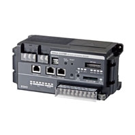
Easily installable and variously connectable sensor network server.
Related Contents
- Features
- Lineup
- Specifications
- Dimensions
- Catalog / Manual / CAD / Software
last update: April 14, 2026
Hardware Specifications
| Items | Details | ||
|---|---|---|---|
| Power Supply Voltage | 100-240 VAC (-15 to +10%), 50/60 Hz | ||
| Power Consumption | 15 VA or less | ||
| Maximum No. of
Measurement Devices |
LAN | 100 units (In case of a measurement device that can be connected with LAN
directly, there are restrictions to the connection method.) *1 |
|
| RS-485 | 124 devices (31 devices x 4 ports) | ||
| Maximum No. of Measurement Channels | 500 channels (There are restrictions depending on the type of the
measurement device and the collection interval.) |
||
| Collection Interval | 1/5/10/30/60 minutes | ||
| Commu-
nication Interface |
LAN | No. of Ports | 2 ports (one LAN port and one sub-LAN port) |
| Interface | 10BASE-T/100BASE-TX | ||
| Connector | RJ-45 Cross/Straight Automatic Judgment | ||
| RS-485 | No. of Ports | 4 Ports | |
| Communication
Protocol |
CompoWay/F, Modbus RTU | ||
| Maximum No. of
Connected Devices |
31 devices per port (Total: 31 devices x 4 ports = 124 devices) | ||
| Terminating
Resistor |
Incorporated (120 Ω) | ||
| Communication
Speed |
9.6/19.2/38.4 kbps (at the time of shipment from factory: 9.6 kbps) | ||
| Data Bit Length | 7/8 bits (when shipped from factory: 7 bits) | ||
| Stop Bit Length | 1/2 bits (when shipped from factory: 2 bits) | ||
| Vertical Parity | None/Even/Odd (when shipped form factory: Even) | ||
| General-
Purpose Input |
No. of Input Points | One Point (Pulse Input) | |
| Input Pulse Width | 5 ms or more | ||
| Rated Input Voltage | 12-24 VDC, -15% to +10% | ||
| Input Impedance | Approx. 2.2 kΩ | ||
| Input Current | 12 V/5 mA (TYP), 24 V/10 mA (TYP) | ||
| ON/OFF Voltage | 10.2 VDC or more/5.0 VDC or less | ||
| General-
Purpose Output |
No. of Output Points | Four Points (Monitoring Alarm Output) | |
| Maximum Load Voltage/
Current |
30 VDC/50 mA/Point | ||
| ON Resistor | 5 Ω or less | ||
| Display | Display of Operating/Abnormal/Collection State and Monitoring Alarm
Display of Operating State of RS-485 Communications/General-Purpose I/O |
||
| Operation Buttons | RUN/STOP Button, RESET Button, and TEST Button | ||
| DIP Switch | DIP Switch for Setting | ||
| SD Drive | SD Card Drive, SD SAVE Button, and SD BUSY Display | ||
| Insulation Resistance *2 | Between power terminals and FG terminal: 20 MΩ or higher (500 VDC,
megger) Between power terminals and general-purpose input, general purpose outputs 1 to 4, RS-485 communications ports 1 to 4, LAN, sub-LAN, OPTION 1, and OPTION 2 Together: 20 MΩ or higher (500 VDC) Grounding: Between FG terminal and OPTION 1/OPTION 2: 20 MΩ or higher (500 VDC) |
||
| Withstand Voltage *2 | Between power terminals and FG terminal: 1500 VAC for one minute
Between power terminals and general-purpose input, general purpose outputs 1 to 4, RS-485 communications ports 1 to 4, LAN, sub-LAN, OPTION 1, and OPTION 2 Together: 1500 VAC for one minute Grounding: Between FG terminal and OPTION 1/OPTION 2: 500 VAC for one minute |
||
| Vibration Resistance *2 | 10 to 150 Hz: Half amplitude of 0.1 mm, acceleration of 15 m/s2,
sweep 8 min. x 10 times for each direction of 3 axes |
||
| Shock Resistance *2 | 150 m/s2, 6 directions of up, down, right, left, front and back, 3 times each | ||
| Operating Ambient Temperature/
Humidity *2 |
-10 to +55°C / 25-85%RH (no freezing and condensation) | ||
| Storage Ambient Temperature *2 | -25 to +65°C (batteries are excluded) | ||
| Storage Humidity *2 | Relative Humidity 25-85%RH | ||
| Protective Structure | IP20 | ||
| Supported Memory Card | SD card (optional, up to 2 GB), SDHC card (optional, up to 32 GB)
Supported Format: FAT16/FAT32 *3 Recommended Product: HMC-SD492(4GB), HMC-SD291(2GB) *4 If you are using a third-party card, SD card for industrial use is recommended. |
||
| Data Protection of Internal Volatile
Memory |
Lithium battery, five-year life (reference value, at ambient temperature of
23°C) |
||
| Built-in Clock | Supporting leap years from 2010 to 2099
Precision: ±40 sec/month (at ambient temperature of 23°C) |
||
| Mounting | Screw or use DIN rail to mount it | ||
| Weight | Approx. 0.7 kg | ||
| Accessories | Operation Manual, Startup Guide
Memory backup battery (stored inside the top panel of the EQ100-E) DVD-ROM (containing graph software EQ-Viewer and manual) |
||
*1. The number of connectable measurement devices is different depending on the connection method. For details, refer to
the User's Manual.
The measurement device means the device connected with EQ100-E to measure data, such as each sensor or PLC.
*2. When an SD card is not inserted
*3. The SDXC card is not supported and cannot be used.
If the SD/SDHC is not formatted, use the format software to format it.
For the SD card formatting software distribution site, refer to the following URL.
https: //www.sdcard.org/jp/downloads/formatter_4/
*4. Orders for HMC-SD291 will be accepted until the end of March 2022.
Software Specifications
| Items | Details | |
|---|---|---|
| Operation Mode | Normal Mode | Modes when operated normally |
| Safe Mode | Modes when recovering from disasters or maintaining the device | |
| Logging Function | The logging function is configured with collected data and event logs.
Collected data: The data collected from measurement devices are saved in the internal memory. Event Log: Log of EQ100-E monitoring alarm, device alarm, and internal events are saved in the internal memory as event log. |
|
| Setup Function | The setup file needed for EQ100-E can be created using EQ-Manager
included in the accessory software. The setup file can be written in EQ100-E from EQ-Manager, a web screen, or the SD card in which the setup file is stored. |
|
| Time
Synchronization |
Synchronization with
EQ Server |
EQ100-E synchronizes time with the EQ Server (PC used as a server). |
| Synchronization with
SNTP Server |
EQ100-E synchronizes time with the SNTP server. | |
| Network Connection | LAN connection port: The connectable functions/devices are as follows:
A host system (EQ server, EQ-Manager, SMTP server, SNTP server, FTP server, and FTP client), a personal computer (web browser), and measurement device Sub-LAN connection port: Connectable functions/devices are as follows: Measurement devices, personal computers (web browser) |
|
| Web Function (Japanese, English, and
Chinese languages are supported) |
You can confirm operating condition, operate the EQ100-E, view simple
graphs, and perform maintenance through a web browser on a computer connected to the LAN or sub-LAN connection port. The operation channel cannot be displayed as a graph. |
|
| Taking Out Internal Data File | The following four methods are available: | |
| (1) Collecting by EQ Server | The EQ server collects the collected data and event logs stored in the
EQ100-E internal memory via the network. |
|
| (2) Operations on Web
UI Screen |
The collected data or event logs stored in the EQ100-E internal memory
is downloaded to the personal computer by operations on the Web UI screen. |
|
| (3) SD Card Output | Any of the following operations outputs the collected data and log files
stored in the EQ100-E internal memory to an SD card. • Pressing the SD card save button on the EQ100-E front side • Web UI operations: SD card data output operations If the SD card output setting is configured as "Yes" by EQ-Manager, the collected data stored in the EQ100-E internal memory is saved on an SD card once a day. |
|
| (4) FTP Transfer | FTP server and FTP client functions are available.
• FTP server function: Acquires the collected data files stored in the EQ100-E internal memory via an FTP client and the collected data on an SD card attached to EQ100-E or an event log. • FTP client function: Sends collected data files stored in the EQ100-E internal memory to the FTP server from EQ100-E. |
|
| Monitoring
Alarm |
Function | Alarm is set off when collected data exceeds the upper or lower limit.
Output to a general-purpose output terminal is available as well. |
| Email Notification | Function: Monitoring Alarm Email | |
| Log to Internal Memory | Monitoring alarm occurrence is saved into the internal memory.
The event log can be checked on the Web UI screen and outputted as an event log file. |
|
| Status Indication | The monitoring alarm indicator is turned ON. | |
| Device Alarm
Detection |
Function | Detects a device failure, setup/status failure, device failure,
communication failure, or monitoring process failure. |
| Email Notification | Function: Device alarm notification email | |
| Status Indication | Lighting, blinking, blinking in long cycles, temporary lighting of the
device alarm indicator lamp |
|
| Log to Internal Memory | An occurred device alarm is saved into the internal memory. It can be
outputted as an event log file. |
|
| Contact Output | Function | An alarm can be outputted through the general-purpose output terminal
when the monitoring condition is met. |
| Email
Notification |
Function | • Monitoring alarm notification email: Sent upon a monitoring alarm
occurrence. • Device alarm notification email: Sent upon an occurrence of a device failure or an abnormality of setup/status, device, communications, or monitoring process of EQ100-E. • Periodic alarm: An e-mail with the main text is written by the user is sent at a specified time. • Test email: Sent by Web UI operations to check the email notification settings or the state of communications with the SMTP server. Note: The SMTP function with email transmission authentication supports: • POP before SMTP • POP before SMTP(APOP) • SMTP AUTH PLAIN • SMTP AUTH CRAM-MD5 |
| Maintenance
Function |
Communication Test | Communications with connected measurement devices are
continuously performed to check stability of the communications with measurement devices. Collected data are not saved. |
| Clock Setting | The time is configured for the built-in clock of the EQ100-E. | |
| General-Purpose
Output |
The general-purpose output terminals of the main unit are operated ON
or OFF. |
|
| FTP Test Transfer | FTP transfer from the EQ100 to the FTP server is tested. | |
| Firmware Update | The firmware of the EQ100-E is updated. The firmware can be updated
by any of the following methods: • By Web UI operations, the firmware is transferred from the PC to EQ100-E to update. • By inserting an SD card containing the firmware to EQ100-E to update the firmware. |
|
Sensor (measurement device) types and maximum number of measurement channels
| Connection
Methods |
Connection
Types |
Connectable
Sensor Types |
Maximum No. of
Connected Devices *3 |
Maximum No. of Measurement
Channels *1 |
|
|---|---|---|---|---|---|
| Collection
Interval: one minute |
Five minutes
or more |
||||
| RS-485 *4 | RS-485
Connected Sensor |
Power Sensor
Other Sensors |
124 devices
(31 devices/port x 4 ports |
160 channels
(40 channels/port) |
500 channels
(200 channels/port) |
| LAN | LAN Connection
Sensor |
Power Logger
Environment Sensor |
100 devices | 500 channels | 500 channels |
| Sensor via Wireless Unit Slave | 30 devices *2
(14 sensors/slave unit) |
40 channels | 120 channels | ||
| Wireless Environment Sensor | 30 devices *2 | Follow the restrictions on the number of
connected devices. |
|||
| PLC | CJ-Series
NJ/NX1P2-Series |
10 devices | 500 channels | 500 channels | |
| Pulse Input | - | One point | One channel | One channel | |
| Operation
Channel |
This channel is obtained by treating
the measurement channel by arithmetic processing. |
- | 100 channels | 100 channels | |
*1. The maximum number of measurement channels of EQ100-E is 500, including all sensors (measurement devices) and
operation channels.
*2. One slave device of wireless sensor is calculated as one device regardless of the number of master devices connected
with LAN and the number of connected relay devices.
*3. No. of connected KM-N1-FLK devices = No. of measurement circuits (No. of the measurement circuits set on the power
sensor main unit), No. of connected KM1 devices = No. of units (No. of master and slave devices)
*4. For RS-485 connection, either CompWay/F or ModbusRTU can be selected for each communication port.
last update: April 14, 2026