WL-N / WLG
Two-circuit Limit Switch
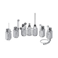
Two-circuit limit switches that can be selected to match the operating environment and application WL-N/Basic models, WLG/High-sensitivity and High-precision models
Related Contents
- Features
- Lineup
- Specifications
- Dimensions
- Catalog / Manual / CAD / Software
last update: April 1, 2025
General-purpose Switches
Ratings
Screw terminals
Without Operation Indicator
Basic models (WL-N)
| Ratings | Non-inductive load (A) | Inductive load (A) | |||||||
|---|---|---|---|---|---|---|---|---|---|
| Basic models (WL-N) | Basic models (WL-N) | ||||||||
| Resistive load | Lamp load | Inductive load | Motor load | ||||||
| Voltage (V) | NC | NO | NC | NO | NC | NO | NC | NO | |
| AC | 125 | 10 | 3 | 1.5 | 10 | 5 | 2.5 | ||
| 250 | 10 | 2 | 1 | 10 | 3 | 1.5 | |||
| 500 | 10 | 1.5 | 0.8 | 3 | 1.5 | 0.8 | |||
| DC | 8 | 10 | 6 | 3 | 10 | 6 | |||
| 14 | 10 | 6 | 3 | 10 | 6 | ||||
| 30 | 6 | 4 | 3 | 6 | 4 | ||||
| 125 | 0.8 | 0.2 | 0.2 | 0.8 | 0.2 | ||||
| 250 | 0.4 | 0.1 | 0.1 | 0.4 | 0.1 | ||||
High-sensitivity and High-precision models (WLG)
| Ratings | Non-inductive load (A) | ||
|---|---|---|---|
| High-sensitivity and High-precision models (WLG)
Horizontal plunger models (WLSD[]) |
|||
| Resistive load | |||
| Voltage (V) | NC | NO | |
| AC | 125 | 5 | |
| 250 | 5 | ||
| DC | 125 | 0.4 | |
| 250 | 0.2 | ||
With Operation Indicator (LED)
Basic models (WL-N)
| Ratings | Non-inductive load (A) | Inductive load (A) | |||||||
|---|---|---|---|---|---|---|---|---|---|
| Basic models (WL-N) | Basic models (WL-N) | ||||||||
| Resistive load | Lamp load | Inductive load | Motor load | ||||||
| Voltage (V) | NC | NO | NC | NO | NC | NO | NC | NO | |
| AC | 115 | 10 | 3 | 1.5 | 10 | 5 | 2.5 | ||
| DC | 12 | 10 | 6 | 3 | 10 | 6 | |||
| 24 | 6 | 4 | 3 | 6 | 4 | ||||
| 48 | 3 | 2 | 1.5 | 3 | 0.2 | ||||
| 115 | 0.8 | 0.2 | 0.8 | 0.1 | |||||
High-sensitivity and High-precision models (WLG)
| Ratings | Non-inductive load (A) | ||
|---|---|---|---|
| High-sensitivity and High-precision models (WLG)
Horizontal plunger models (WLSD[]) |
|||
| Resistive load | |||
| Voltage (V) | NC | NO | |
| AC | 115 | 5 | |
| DC | 115 | 0.4 | |
With Operation Indicators (Neon Lamps)
Basic models (WL-N)
| Ratings | Non-inductive load (A) | Inductive load (A) | |||||||
|---|---|---|---|---|---|---|---|---|---|
| Basic models (WL-N) | Basic models (WL-N) | ||||||||
| Resistive load | Lamp load | Inductive load | Motor load | ||||||
| Voltage (V) | NC | NO | NC | NO | NC | NO | NC | NO | |
| AC | 125 | 10 | 3 | 1.5 | 10 | 5 | 2.5 | ||
| 250 | 10 | 2 | 1 | 10 | 3 | 1.5 | |||
High-sensitivity and High-precision models (WLG)
| Ratings | Non-inductive load (A) | ||
|---|---|---|---|
| High-sensitivity and High-precision models (WLG)
Horizontal plunger models (WLSD[]) |
|||
| Resistive load | |||
| Voltage (V) | NC | NO | |
| AC | 125 | 5 | |
| 250 | 5 | ||
Note: 1. The above figures are for steady-state currents.
2. Inductive loads have a power factor of 0.4 min. (AC) and a time constant of 7 ms max. (DC).
3. A lamp load has an inrush current of 10 times the steady-state current.
4. A motor load has an inrush current of 6 times the steady-state current.
2. Inductive loads have a power factor of 0.4 min. (AC) and a time constant of 7 ms max. (DC).
3. A lamp load has an inrush current of 10 times the steady-state current.
4. A motor load has an inrush current of 6 times the steady-state current.
Allowable Inrush Current/Minimum Applicable Load
| Operating characteristics type | Basic models (WL-N) | High-sensitivity and
High-precision models (WLG) Horizontal plunger models (WLSD[]) |
|
|---|---|---|---|
| Inrush current | NC | 30 A max. | 15 A max. |
| NO | 20 A max. | 10 A max. | |
| Minimum applicable load | 5 VDC 1 mA, resistive load, P level | 5 VDC 1 mA, resistive load, P level | |
Operation Indicator
| Operation indicator type | LED | Neon lamp |
|---|---|---|
| Rated voltage | 10 to 115 VAC/DC | 125 to 250 VAC |
| Leakage current
(Reference value) |
Approx. 0.4 mA at 10 VAC/DC
Approx. 0.5 mA at 115 VAC/DC |
Approx. 0.6 mA at 125 VAC
Approx. 1.9 mA at 250 VAC |
Direct-wired connector and Pre-wired Connector Type
Connector DC Specifications: With Operation Indicators (LEDs)
Basic models (WL-N)
| Ratings | Non-inductive load (A) | Inductive load (A) | |||||||
|---|---|---|---|---|---|---|---|---|---|
| Basic models (WL-N) | Basic models (WL-N) | ||||||||
| Resistive load | Lamp load | Inductive load | Motor load | ||||||
| Voltage (V) | NC | NO | NC | NO | NC | NO | NC | NO | |
| DC | 12 | 3 | 3 | 3 | 3 | ||||
| 24 | 3 | 3 | 3 | 3 | |||||
| 48 | 4 | 2 | 1.5 | 3 | 2 | ||||
| 115 | 0.8 | 0.2 | 0.2 | 0.8 | 0.2 | ||||
High-sensitivity and High-precision models (WLG)
| Ratings | Non-inductive load (A) | ||
|---|---|---|---|
| High-sensitivity and High-precision models (WLG)
Horizontal plunger models (WLSD[]) |
|||
| Resistive load | |||
| Voltage (V) | NC | NO | |
| DC | 115 | 0.4 | |
Connector AC Specifications: With Operation Indicators (LEDs)
Basic models (WL-N)
| Ratings | Non-inductive load (A) | Inductive load (A) | |||||||
|---|---|---|---|---|---|---|---|---|---|
| Basic models (WL-N) | Basic models (WL-N) | ||||||||
| Resistive load | Lamp load | Inductive load | Motor load | ||||||
| Voltage (V) | NC | NO | NC | NO | NC | NO | NC | NO | |
| AC | 115 | 3 | 3 | 1.5 | 3 | 3 | 2.5 | ||
High-sensitivity and High-precision models (WLG)
| Ratings | Non-inductive load (A) | ||
|---|---|---|---|
| High-sensitivity and High-precision models (WLG)
Horizontal plunger models (WLSD[]) |
|||
| Resistive load | |||
| Voltage (V) | NC | NO | |
| AC | 115 | 3 | |
Note: 1. The above figures are for steady-state currents.
2. Inductive loads have a power factor of 0.4 min. (AC) and a time constant of 7 ms max. (DC).
3. A lamp load has an inrush current of 10 times the steady-state current.
4. A motor load has an inrush current of 6 times the steady-state current.
2. Inductive loads have a power factor of 0.4 min. (AC) and a time constant of 7 ms max. (DC).
3. A lamp load has an inrush current of 10 times the steady-state current.
4. A motor load has an inrush current of 6 times the steady-state current.
Minimum Applicable Load
| Operating characteristics type | Basic models (WL-N) | High-sensitivity and
High-precision models (WLG) Horizontal plunger models (WLSD[]) |
|---|---|---|
| Minimum applicable load | 5 VDC 1 mA, resistive load, P level | 5 VDC 1 mA, resistive load, P level |
Operation Indicator
| Operation indicator type | LED | Neon lamp |
|---|---|---|
| Rated voltage | 10 to 115 VAC/DC | 125 to 250 VAC |
| Leakage current
(Reference value) |
Approx. 0.4 mA at 10 VAC/DC
Approx. 0.5 mA at 115 VAC/DC |
Approx. 0.6 mA at 125 VAC
Approx. 1.9 mA at 250 VAC |
Characteristics
| Operating characteristics type | Basic models (WL-N) | High-sensitivity and
High-precision models (WLG) |
|
|---|---|---|---|
| Permissible
operating frequency |
Mechanical | 120 operations/minute | |
| Electrical | 30 operations/minute | ||
| Rated frequency | 50/60 Hz | ||
| Permissible operating speed | 1 mm/s to 1 m/s (in case of WLCA2-N) | ||
| Insulation resistance | 100 MΩ min. (at 500 VDC) | ||
| Contact resistance | 25 mΩ max. (initial value for the built-in switch) | ||
| Vibration resistance | Malfunction | 10 to 55 Hz, 1.5-mm double amplitude | |
| Shock | Destruction | 1,000 m/s2 max. | |
| Malfunction | 300 m/s2 max. *2 | ||
| Durability *1 | Mechanical | 15,000,000 operations min.
(Flexible Rod models: 10,000,000 operations min.) |
10,000,000 operations min. |
| Electrical | 750,000 operations min. (Screw
terminals: without operation indicators, 3 A at 250 VAC, resistive load. Direct-wire connector/Pre-wired connector: with operation indicators, 0.8 A at 115 VDC, resistive load) *3 |
500,000 operations min. (3 A at 250
VAC, resistive load), but for high- precision models |
|
| Ambient operating temperature | -10 to +80°C (with no icing) | ||
| Ambient operating humidity | 35 to 95%RH | ||
| Degree of protection *4 | IP67 (EN60947-5-1) | ||
| Weight | Approx. 255 g (in case of WLCA2-N) | Approx. 270 g (in case of WLGCA2) | |
Note: The above figures are initial values.
*1. The values are calculated at an operating temperature of +5°C to +35°C, and an operating humidity of 40% to 70%RH.
Contact your OMRON sales representative for more detailed information on other operating environments.
*2. Except Switches with Flexible Rod Actuators.
*3. Horizontal plunger models: 500,000 operations min. (3 A at 250 VAC, resistive load)
*4. The degree of protection is tested using the method specified by the standard (EN60947-5-1). Confirm that sealing
properties are sufficient for the operating conditions and environment beforehand.
| Operating characteristics type | Basic models (WL-N) | High-sensitivity and
High-precision models (WLG) |
|||
|---|---|---|---|---|---|
| Wiring Specifications | Screw
terminals |
Direct-wire connector/
Pre-wired Connector Models |
Screw
terminals |
Direct-wire connector/
Pre-wired Connector Models |
|
| Dielectric
strength |
Between terminals
of the same polarity |
1,000 VAC,
50/60 Hz for 1 min * |
600 VAC,
50/60 Hz for 1 min * |
600 VAC,
50/60 Hz for 1 min * |
600 VAC,
50/60 Hz for 1 min * |
| Between current-
carrying metal part and ground |
2,200 VAC,
50/60 Hz for 1 min |
1,500 VAC,
50/60 Hz for 1 min |
1,500 VAC,
50/60 Hz for 1 min |
1,500 VAC,
50/60 Hz for 1 min |
|
| Between each
terminal and non- current-carrying metal part |
2,200 VAC,
50/60 Hz for 1 min |
1,500 VAC,
50/60 Hz for 1 min |
1,500 VAC,
50/60 Hz for 1 min |
1,500 VAC,
50/60 Hz for 1 min |
|
* Excluding those with operation indicators.
Environment-resistant Limit Switches
Ratings
Screw terminals/Direct-wire cable
Without Operation Indicator
Basic models (WL-N)
| Ratings | Non-inductive load (A) | Inductive load (A) | |||||||
|---|---|---|---|---|---|---|---|---|---|
| Basic models (WL-N) | Basic models (WL-N) | ||||||||
| Resistive load | Lamp load | Inductive load | Motor load | ||||||
| Voltage (V) | NC | NO | NC | NO | NC | NO | NC | NO | |
| AC | 125 | 10 | 3 | 1.5 | 10 | 5 | 2.5 | ||
| 250 | 10 | 2 | 1 | 10 | 3 | 1.5 | |||
| 500 | 10 | 1.5 | 0.8 | 3 | 1.5 | 0.8 | |||
| DC | 8 | 10 | 6 | 3 | 10 | 6 | |||
| 14 | 10 | 6 | 3 | 10 | 6 | ||||
| 30 | 6 | 4 | 3 | 6 | 4 | ||||
| 125 | 0.8 | 0.2 | 0.2 | 0.8 | 0.2 | ||||
| 250 | 0.4 | 0.1 | 0.1 | 0.4 | 0.1 | ||||
High-sensitivity and High-precision models (WLG)
| Ratings | Non-inductive load (A) | ||
|---|---|---|---|
| High-sensitivity and High-precision models (WLG) | |||
| Resistive load | |||
| Voltage (V) | NC | NO | |
| AC | 125 | 5 | |
| 250 | 5 | ||
| DC | 125 | 0.4 | |
| 250 | 0.2 | ||
With Operation Indicator (LED)
Basic models (WL-N)
| Ratings | Non-inductive load (A) | Inductive load (A) | |||||||
|---|---|---|---|---|---|---|---|---|---|
| Basic models (WL-N) | Basic models (WL-N) | ||||||||
| Resistive load | Lamp load | Inductive load | Motor load | ||||||
| Voltage (V) | NC | NO | NC | NO | NC | NO | NC | NO | |
| AC | 115 | 10 | 3 | 1.5 | 10 | 5 | 2.5 | ||
| DC | 12 | 10 | 6 | 3 | 10 | 6 | |||
| 24 | 6 | 4 | 3 | 6 | 4 | ||||
| 48 | 3 | 2 | 1.5 | 3 | 0.2 | ||||
| 115 | 0.8 | 0.2 | 0.8 | 0.1 | |||||
High-sensitivity and High-precision models (WLG)
| Ratings | Non-inductive load (A) | ||
|---|---|---|---|
| High-sensitivity and High-precision models (WLG) | |||
| Resistive load | |||
| Voltage (V) | NC | NO | |
| AC | 115 | 5 | |
| DC | 115 | 0.4 | |
With Operation Indicators (Neon Lamps)
Basic models (WL-N)
| Ratings | Non-inductive load (A) | Inductive load (A) | |||||||
|---|---|---|---|---|---|---|---|---|---|
| Basic models (WL-N) | Basic models (WL-N) | ||||||||
| Resistive load | Lamp load | Inductive load | Motor load | ||||||
| Voltage (V) | NC | NO | NC | NO | NC | NO | NC | NO | |
| AC | 125 | 10 | 3 | 1.5 | 10 | 5 | 2.5 | ||
| 250 | 10 | 2 | 1 | 10 | 3 | 1.5 | |||
High-sensitivity and High-precision models (WLG)
| Ratings | Non-inductive load (A) | ||
|---|---|---|---|
| High-sensitivity and High-precision models (WLG) | |||
| Resistive load | |||
| Voltage (V) | NC | NO | |
| AC | 125 | 5 | |
| 250 | 5 | ||
Note: 1. The above figures are for steady-state currents.
2. Inductive loads have a power factor of 0.4 min. (AC) and a time constant of 7 ms max. (DC).
3. A lamp load has an inrush current of 10 times the steady-state current.
4. A motor load has an inrush current of 6 times the steady-state current.
2. Inductive loads have a power factor of 0.4 min. (AC) and a time constant of 7 ms max. (DC).
3. A lamp load has an inrush current of 10 times the steady-state current.
4. A motor load has an inrush current of 6 times the steady-state current.
Allowable Inrush Current/ Minimum applicable load
| Operating characteristics type | Basic models (WL-N) | High-sensitivity and
High-precision models (WLG) |
|
|---|---|---|---|
| Inrush current | NC | 30 A max. | 15 A max. |
| NO | 20 A max. | 10 A max. | |
| Minimum applicable load | 5 VDC 1 mA, resistive load, P level | 5 VDC 1 mA, resistive load, P level | |
Operation Indicator
| Operation indicator type | LED | Neon lamp |
|---|---|---|
| Rated voltage | 10 to 115 VAC/DC | 125 to 250 VAC |
| Leakage current
(Reference value) |
Approx. 0.4 mA at 10 VAC/DC
Approx. 0.5 mA at 115 VAC/DC |
Approx. 0.6 mA at 125 VAC
Approx. 1.9 mA at 250 VAC |
Characteristics
| Operating characteristics type | Basic models (WL-N) | High-sensitivity and
High-precision models (WLG) |
|
|---|---|---|---|
| Permissible operating
frequency |
Mechanical | 120 operations/minute | |
| Electrical | 30 operations/minute | ||
| Rated frequency | 50/60 Hz | ||
| Permissible operating speed | 1 mm/s to 1 m/s (in case of WLCA2-N) | ||
| Insulation resistance | 100 MΩ min. (at 500 VDC) | ||
| Contact resistance | 25 mΩ or less (default value, built-in switch only) | ||
| Vibration resistance | Malfunction | 10 to 55 Hz, 1.5-mm double amplitude *2 | |
| Shock | Destruction | 1,000 m/s2 max. | |
| Malfunction | 300m/s2 max. *2 | ||
| Durability *1 | Mechanical | 15,000,000 operations min. | 10,000,000 operations min. *3 |
| Electrical | 750,000 operations min. (3 A at 250
VAC, resistive load) *4 |
500,000 operations min. (3 A at 250
VAC, resistive load) *4 |
|
| Ambient operating temperature | -10 to +80°C (with no icing) *5 | ||
| Ambient operating humidity | 35 to 95%RH | ||
| Degree of protection *6 | IP67 (EN60947-5-1) | ||
| Weight | Approx. 250 g (for WLCL-TH-N) | Approx. 250 g (for WLCL-TH-N) | |
Note: The above figures are initial values.
*1. The values are calculated at an operating temperature of +5°C to +35°C, and an operating humidity of 40% to 70%RH.
Contact your OMRON sales representative for more detailed information on other operating environments.
*2. Except Switches with Flexible Rod Actuators.
*3. 500,000 operations min. for Weather-resistant models.
*4. In case of models without operation indicators.
*5. For low-temperature models this is -40°C to +40°C (with no icing). For heat-resistant models the range is +5°C to
120°C.
*6. The degree of protection is tested using the method specified by the standard (EN60947-5-1). Confirm that sealing
properties are sufficient for the operating conditions and environment beforehand.
| Operating characteristics type | Basic models (WL-N) | High-sensitivity and
High-precision models (WLG) |
|
|---|---|---|---|
| Wiring Specifications | Screw terminals/
Direct-wire cable models |
Screw terminals/
Direct-wire cable models |
|
| Dielectric
strength |
Between terminals of the same polarity | 1,000 VAC, 50/60 Hz for 1 min * | 600 VAC, 50/60 Hz for 1 min * |
| Between current-carrying metal part
and ground |
2,200 VAC, 50/60 Hz for 1 min | 1,500 VAC, 50/60 Hz for 1 min | |
| Between each terminal and non-
current-carrying metal part |
2,200 VAC, 50/60 Hz for 1 min | 1,500 VAC, 50/60 Hz for 1 min | |
* Except models with operation indicators.
Spatter-prevention Switches
Ratings
Screw terminals
With Operation Indicator
Basic models (WL-N)
| Ratings | Non-inductive load (A) | Inductive load (A) | |||||||
|---|---|---|---|---|---|---|---|---|---|
| Basic models (WL-N) | Basic models (WL-N) | ||||||||
| Resistive load | Lamp load | Inductive load | Motor load | ||||||
| Voltage (V) | NC | NO | NC | NO | NC | NO | NC | NO | |
| AC | 115 | 10 | 3 | 1.5 | 10 | 5 | 2.5 | ||
| DC | 12 | 10 | 6 | 3 | 10 | 6 | |||
| 24 | 6 | 4 | 3 | 6 | 4 | ||||
| 48 | 3 | 2 | 1.5 | 3 | 0.2 | ||||
| 115 | 0.8 | 0.2 | 0.8 | 0.1 | |||||
High-sensitivity and High-precision models (WLG)
| Ratings | Non-inductive load (A) | ||
|---|---|---|---|
| High-sensitivity and High-precision models (WLG) | |||
| Resistive load | |||
| Voltage (V) | NC | NO | |
| AC | 115 | 5 | |
| DC | 115 | 0.4 | |
With Operation Indicators (Neon Lamps)
Basic models (WL-N)
| Ratings | Non-inductive load (A) | Inductive load (A) | |||||||
|---|---|---|---|---|---|---|---|---|---|
| Basic models (WL-N) | Basic models (WL-N) | ||||||||
| Resistive load | Lamp load | Inductive load | Motor load | ||||||
| Voltage (V) | NC | NO | NC | NO | NC | NO | NC | NO | |
| AC | 125 | 10 | 3 | 1.5 | 10 | 5 | 2.5 | ||
| 250 | 10 | 2 | 1 | 10 | 3 | 1.5 | |||
High-sensitivity and High-precision models (WLG)
| Ratings | Non-inductive load (A) | ||
|---|---|---|---|
| High-sensitivity and High-precision models (WLG) | |||
| Resistive load | |||
| Voltage (V) | NC | NO | |
| AC | 125 | 5 | |
| 250 | 5 | ||
Note: 1. The above figures are for steady-state currents.
2. Inductive loads have a power factor of 0.4 min. (AC) and a time constant of 7 ms max. (DC).
3. A lamp load has an inrush current of 10 times the steady-state current.
4. A motor load has an inrush current of 6 times the steady-state current.
2. Inductive loads have a power factor of 0.4 min. (AC) and a time constant of 7 ms max. (DC).
3. A lamp load has an inrush current of 10 times the steady-state current.
4. A motor load has an inrush current of 6 times the steady-state current.
Allowable Inrush Current/Minimum Applicable Load
| Operating characteristics type | Basic models (WL-N) | High-sensitivity and
High-precision models (WLG) |
|
|---|---|---|---|
| Inrush current | NC | 30 A max. | 15 A max. |
| NO | 20 A max. | 10 A max. | |
| Minimum applicable load | 5 VDC 1 mA, resistive load, P level | 5 VDC 1 mA, resistive load, P level | |
Operation Indicator
| Operation indicator type | LED | Neon lamp |
|---|---|---|
| Rated voltage | 10 to 115 VAC/DC | 125 to 250 VAC |
| Leakage current
(Reference value) |
Approx. 0.4 mA at 10 VAC/DC
Approx. 0.5 mA at 115 VAC/DC |
Approx. 0.6 mA at 125 VAC
Approx. 1.9 mA at 250 VAC |
Pre-wired connectors
Connector DC Specifications: With Operation Indicators (LEDs)
Basic models (WL-N)
| Ratings | Non-inductive load (A) | Inductive load (A) | |||||||
|---|---|---|---|---|---|---|---|---|---|
| Basic models (WL-N) | Basic models (WL-N) | ||||||||
| Resistive load | Lamp load | Inductive load | Motor load | ||||||
| Voltage (V) | NC | NO | NC | NO | NC | NO | NC | NO | |
| DC | 12 | 3 | 3 | 3 | 3 | ||||
| 24 | 3 | 3 | 3 | 3 | |||||
| 48 | 4 | 2 | 1.5 | 3 | 2 | ||||
| 115 | 0.8 | 0.2 | 0.2 | 0.8 | 0.2 | ||||
High-sensitivity and High-precision models (WLG)
| Ratings | Non-inductive load (A) | ||
|---|---|---|---|
| High-sensitivity and High-precision models (WLG) | |||
| Resistive load | |||
| Voltage (V) | NC | NO | |
| DC | 115 | 0.4 | |
Note: 1. The above figures are for steady-state currents.
2. Inductive loads have a power factor of 0.4 min. (AC) and a time constant of 7 ms max. (DC).
3. A lamp load has an inrush current of 10 times the steady-state current.
4. A motor load has an inrush current of 6 times the steady-state current
2. Inductive loads have a power factor of 0.4 min. (AC) and a time constant of 7 ms max. (DC).
3. A lamp load has an inrush current of 10 times the steady-state current.
4. A motor load has an inrush current of 6 times the steady-state current
Minimum Applicable Load
| Operating characteristics type | Basic models (WL-N) | High-sensitivity and
High-precision models (WLG) |
|---|---|---|
| Minimum applicable load | 5 VDC 1 mA, resistive load, P level | 5 VDC 1 mA, resistive load, P level |
Operation Indicator
| Operation indicator type | LED | Neon lamp |
|---|---|---|
| Rated voltage | 10 to 115 VAC/DC | 125 to 250 VAC |
| Leakage current
(Reference value) |
Approx. 0.4 mA at 10 VAC/DC;
Approx. 0.5 mA at 115 VAC/DC |
Approx. 0.6 mA at 125 VAC;
Approx. 1.9 mA at 250 VAC |
Characteristics
| Operating characteristics type | Basic models (WL-N) | High-sensitivity and
High-precision models (WLG) |
|
|---|---|---|---|
| Permissible operating
frequency |
Mechanical | 120 operations/minute | |
| Electrical | 30 operations/minute | ||
| Rated frequency | 50/60 Hz | ||
| Permissible operating speed | 1 mm/s to 1 m/s (for WLCA2-LDS-N) | ||
| Insulation resistance | 100 MΩ min. (at 500 VDC) | ||
| Contact resistance | 25 mΩ max. (initial value for the built-in switch) | ||
| Vibration resistance | Malfunction | 10 to 55 Hz, 1.5-mm double amplitude | |
| Shock | Destruction | 1,000 m/s2 max. | |
| Malfunction | 300 m/s2 max. | ||
| Durability * | Mechanical | 15,000,000 operations min. | 10,000,000 operations min. |
| Electrical | 750,000 operations min. (3 A at 115
VAC, resistive load) *2 |
500,000 operations min. (3 A at 115
VAC, resistive load) *2 |
|
| Ambient operating temperature | -10 to +80°C (with no icing) | ||
| Ambient operating humidity | 35 to 95%RH | ||
| Degree of protection *3 | IP67 (EN60947-5-1) | ||
| Weight | Approx. 255 g (in case of WLCA2-
LDS-N) |
Approx. 270 g (in case of WLGCA2-
LDS) |
|
Note: The above figures are initial values.
*1. The values are calculated at an operating temperature of +5°C to +35°C, and an operating humidity of 40% to 70%RH.
Contact your OMRON sales representative for more detailed information on other operating environments.
*2. In case of models with operation indicators (LEDs).
*3. The degree of protection is tested using the method specified by the standard (EN60947-5-1). Confirm that sealing
properties are sufficient for the operating conditions and environment beforehand.
| Operating characteristics type | Basic models (WL-N) | High-sensitivity and
High-precision models (WLG) |
|||
|---|---|---|---|---|---|
| Wiring Specifications | Screw
terminals |
Direct-wire connector
and Pre-wired Connector Models |
Screw
terminals |
Direct-wire connector
and Pre-wired Connector Models |
|
| Dielectric
strength |
Between terminals
of the same polarity |
1,000 VAC,
50/60 Hz for 1 min * |
600 VAC,
50/60 Hz for 1 min * |
600 VAC,
50/60 Hz for 1 min * |
600 VAC,
50/60 Hz for 1 min * |
| Between current-
carrying metal part and ground |
2,200 VAC,
50/60 Hz for 1 min |
1,500 VAC,
50/60 Hz for 1 min |
1,500 VAC,
50/60 Hz for 1 min |
1,500 VAC,
50/60 Hz for 1 min |
|
| Between each
terminal and non- current carrying metal part |
2,200 VAC,
50/60 Hz for 1 min |
1,500 VAC,
50/60 Hz for 1 min |
1,500 VAC,
50/60 Hz for 1 min |
1,500 VAC,
50/60 Hz for 1 min |
|
* Excluding those with operation indicators.
Long-life Switches
Ratings
Screw terminals
With Operation Indicator
Basic models (WL-N)
| Ratings | Non-inductive load (A) | Inductive load (A) | |||||||
|---|---|---|---|---|---|---|---|---|---|
| Basic models (WL-N) | Basic models (WL-N) | ||||||||
| Resistive load | Lamp load | Inductive load | Motor load | ||||||
| Voltage (V) | NC | NO | NC | NO | NC | NO | NC | NO | |
| AC | 115 | 10 | 3 | 1.5 | 10 | 5 | 2.5 | ||
| DC | 12 | 10 | 6 | 3 | 10 | 6 | |||
| 24 | 6 | 4 | 3 | 6 | 4 | ||||
| 48 | 3 | 2 | 1.5 | 3 | 0.2 | ||||
| 115 | 0.8 | 0.2 | 0.8 | 0.1 | |||||
High-sensitivity and High-precision models (WLG)
| Ratings | Non-inductive load (A) | ||
|---|---|---|---|
| High-sensitivity and High-precision models (WLG) | |||
| Resistive load | |||
| Voltage (V) | NC | NO | |
| AC | 115 | 5 | |
| DC | 115 | 0.4 | |
Note: 1. The above figures are for steady-state currents.
2. Inductive loads have a power factor of 0.4 min. (AC) and a time constant of 7 ms max. (DC).
3. A lamp load has an inrush current of 10 times the steady-state current.
4. A motor load has an inrush current of 6 times the steady-state current.
2. Inductive loads have a power factor of 0.4 min. (AC) and a time constant of 7 ms max. (DC).
3. A lamp load has an inrush current of 10 times the steady-state current.
4. A motor load has an inrush current of 6 times the steady-state current.
Allowable Inrush Current/Minimum Applicable Load
| Operating characteristics type | Basic models (WL-N) | High-sensitivity/
High-precision models (WLG) |
|
|---|---|---|---|
| Inrush current | NC | 30 A max. | 15 A max. |
| NO | 20 A max. | 10 A max. | |
| Minimum applicable load | 5 VDC 1 mA, resistive load, P level | 5 VDC 1 mA, resistive load, P level | |
Operation Indicator
| Operation indicator type | LED | Neon lamp |
|---|---|---|
| Rated voltage | 10 to 115 VAC/DC | 125 to 250 VAC |
| Leakage current
(Reference value) |
Approx. 0.4 mA at 10 VAC/DC;
Approx. 0.5 mA at 115 VAC/DC |
Approx. 0.6 mA at 125 VAC;
Approx. 1.9 mA at 250 VAC |
Direct-wire connector and Pre-wired Connector Models Type
DC Connector: With Operation Indicators (LEDs)
Basic models (WL-N)
| Ratings | Non-inductive load (A) | Inductive load (A) | |||||||
|---|---|---|---|---|---|---|---|---|---|
| Basic models (WL-N) | Basic models (WL-N) | ||||||||
| Resistive load | Lamp load | Inductive load | Motor load | ||||||
| Voltage (V) | NC | NO | NC | NO | NC | NO | NC | NO | |
| DC | 12 | 3 | 3 | 3 | 3 | ||||
| 24 | 3 | 3 | 3 | 3 | |||||
| 48 | 4 | 2 | 1.5 | 3 | 2 | ||||
| 115 | 0.8 | 0.2 | 0.2 | 0.8 | 0.2 | ||||
High-sensitivity and High-precision models (WLG)
| Ratings | Non-inductive load (A) | ||
|---|---|---|---|
| High-sensitivity and High-precision models (WLG) | |||
| Resistive load | |||
| Voltage (V) | NC | NO | |
| DC | 115 | 0.4 | |
AC Connector: With Operation Indicators (LEDs)
Basic models (WL-N)
| Ratings | Non-inductive load (A) | Inductive load (A) | |||||||
|---|---|---|---|---|---|---|---|---|---|
| Basic models (WL-N) | Basic models (WL-N) | ||||||||
| Resistive load | Lamp load | Inductive load | Motor load | ||||||
| Voltage (V) | NC | NO | NC | NO | NC | NO | NC | NO | |
| AC | 115 | 3 | 3 | 1.5 | 3 | 3 | 2.5 | ||
High-sensitivity and High-precision models (WLG)
| Ratings | Non-inductive load (A) | ||
|---|---|---|---|
| High-sensitivity and High-precision models (WLG) | |||
| Resistive load | |||
| Voltage (V) | NC | NO | |
| AC | 115 | 3 | |
Note: 1. The above figures are for steady-state currents.
2. Inductive loads have a power factor of 0.4 min. (AC) and a time constant of 7 ms max. (DC).
3. A lamp load has an inrush current of 10 times the steady-state current.
4. A motor load has an inrush current of 6 times the steady-state current.
2. Inductive loads have a power factor of 0.4 min. (AC) and a time constant of 7 ms max. (DC).
3. A lamp load has an inrush current of 10 times the steady-state current.
4. A motor load has an inrush current of 6 times the steady-state current.
Minimum Applicable Load
| Operating characteristics type | Basic models (WL-N) | High-sensitivity and
High-precision models (WLG) |
|---|---|---|
| Minimum applicable load | 5 VDC 1 mA, resistive load, P level | 5 VDC 1 mA, resistive load, P level |
Operation Indicator
| Operation indicator type | LED |
|---|---|
| Rated voltage | 10 to 115 VAC/DC |
| Leakage current
(Reference value) |
Approx. 0.4 mA at 10 VAC/DC;
Approx. 0.5 mA at 115 VAC/DC |
Characteristics
| Operating characteristics type | Basic models (WL-N) | High-sensitivity and
High-precision models (WLG) |
|
|---|---|---|---|
| Permissible operating
frequency |
Mechanical | 120 operations/minute | |
| Electrical | 30 operations/minute | ||
| Rated frequency | 50/60 Hz | ||
| Permissible operating speed | 1 mm/sec to 1 m/sec | ||
| Insulation resistance | 100 MΩ min. (at 500 VDC) | ||
| Contact resistance | 25 mΩ max. (initial value for the built-in switch) | ||
| Vibration resistance | Malfunction | 10 to 55 Hz, 1.5-mm double amplitude | |
| Shock | Destruction | 1,000 m/s2 max. | |
| Malfunction | 300 m/s2 max. | ||
| Durability *1 | Mechanical | 30,000,000 operations min. | |
| Electrical | 30,000,000 operations min. (10
mA at 24 VAC, resistive load) 750,000 operations min. (3 A at 115 VAC, resistive load) |
500,000 operations min. (3 A at
115 VAC, resistive load) |
|
| Ambient operating temperature | -10 to +80°C (with no icing) | ||
| Ambient operating humidity | 35 to 95%RH | ||
| Degree of protection *2 | IP67 (EN60947-5-1) | ||
| Weight | Approx. 255 g (in case of
WLMCA2-LD-N) |
Approx. 270 g (in case of
WLMGCA2-LD) |
|
Note: The above figures are initial values.
*1. The values are calculated at an operating temperature of +5°C to +35°C, and an operating humidity of 40% to 70%RH.
Contact your OMRON sales representative for more detailed information on other operating environments.
*2. The degree of protection is tested using the method specified by the standard (EN60947-5-1). Confirm that sealing
properties are sufficient for the operating conditions and environment beforehand.
| Operating characteristics type | Basic models (WL-N) | High-sensitivity and
High-precision models (WLG) |
|||
|---|---|---|---|---|---|
| Wiring Specifications | Screw
terminals |
Direct-wire connector
and Pre-wired Connector Models |
Screw
terminals |
Direct-wire connector
and Pre-wired Connector Models |
|
| Dielectric
strength |
Between terminals
of the same polarity |
1,000 VAC,
50/60 Hz for 1 min * |
600 VAC,
50/60 Hz for 1 min * |
600 VAC,
50/60 Hz for 1 min * |
600 VAC,
50/60 Hz for 1 min * |
| Between current-
carrying metal part and ground |
2,200 VAC,
50/60 Hz for 1 min |
1,500 VAC,
50/60 Hz for 1 min |
1,500 VAC,
50/60 Hz for 1 min |
1,500 VAC,
50/60 Hz for 1 min |
|
| Between each
terminal and non- current-carrying metal part |
2,200 VAC,
50/60 Hz for 1 min |
1,500 VAC,
50/60 Hz for 1 min |
1,500 VAC,
50/60 Hz for 1 min |
1,500 VAC,
50/60 Hz for 1 min |
|
* Excluding those with operation indicators.
last update: April 1, 2025