NX-ILM400
NX-series IO-Link Master Unit
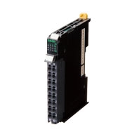
IO-Link makes sensor level information visible and solves the three major issues at manufacturing sites! The screwless clamping terminal block reduces wiring work.
Related Contents
- Features
- Lineup
- Specifications
- Dimensions
- Catalog / Manual / CAD / Software
last update: September 7, 2020
General Specification
| Item | Specification | |
|---|---|---|
| Enclosure | Must be built into a panel. | |
| Grounding methods | Ground to 100 Ω or less. | |
| Operating
environment |
Ambient operating
temperature |
0 to 55°C |
| Ambient operating
humidity |
10% to 95% (with no condensation or icing) | |
| Atmosphere | Must be free from corrosive gases. | |
| Ambient storage
temperature |
-25 to 70°C (with no condensation or icing) | |
| Altitude | 2,000 m max. | |
| Pollution degree | Pollution degree 2 or less: Meets IEC 61010-2-201. | |
| Noise immunity | Conforms to IEC 61000-4-4, 2 kV (power line). | |
| Overvoltage
category |
Category: Meets IEC 61010-2-201. | |
| EMC immunity level | Zone B | |
| Vibration resistance | Conforms to IEC 60068-2-6.
5 to 8.4 Hz with amplitude of 3.5 mm, 8.4 to 150 Hz, acceleration of 9.8 m/s2 100 min each in X, Y, and Z directions (10 sweeps of 10 min each = 100 min total) |
|
| Shock resistance | Conforms to IEC 60068-2-27. 147 m/s2, 3 times each in X, Y, and Z directions | |
| Applicable standards * | UL 61010-2-201, ANSI/ISA 12.12.01, EU: EN 61131-2, NK, LR, RCM, KC,
and IO-Link conformance |
|
* Ask your OMRON representative for the most recent applicable standards for each model.
Unit Specification
| Item | Specification | |
|---|---|---|
| Unit name | IO-Link Master Unit | |
| Model | NX-ILM400 | |
| Number of ports | 4 | |
| Communications
specifications |
Communications protocol | IO-Link protocol |
| Baud rate | COM1: 4.8kbps
COM2: 38.4kbps COM3: 230.4kbps |
|
| Topology | 1:1 | |
| Compliant standards | • IO-Link Interface and System Specification Version1.1.2
• IO-Link Test Specification Version1.1.2 |
|
| Power supply to
devices* in IO-Link Mode or SIO (DI) Mode |
Rated voltage | 24 VDC (20.4 to 28.8 VDC) |
| Maximum load current | 0.2 A/port | |
| Short-circuit protection | Provided. | |
| Digital inputs
(in SIO (DI) Mode) |
Internal I/O common | PNP |
| Rated voltage | 24 VDC (20.4 to 28.8 VDC) | |
| Input current | 5 mA typical (24 VDC) | |
| ON voltage/ON current | 15 VDC min., 2 mA min. | |
| OFF voltage | 5 VDC max. | |
| Input filter time | No filter, 0.25 ms, 0.5 ms, 1 ms (default), 2 ms, 4 ms, 8 ms, 16 ms,
32 ms, 64 ms,128 ms, 256 ms |
|
| Digital outputs
(in SIO (DO) Mode) |
Internal I/O common | PNP |
| Output type | Push-pull | |
| Rated voltage | 24 VDC (20.4 to 28.8 VDC) | |
| Maximum load current | 0.1 A/port | |
| Short-circuit protection | Provided. | |
| Leakage current | 0.1 mA max. | |
| Residual voltage | 1.5 V max. | |
| Digital inputs
for pin 2 (in IO-Link Mode) |
Internal I/O common | PNP |
| Rated voltage | 24 VDC (20.4 to 28.8 VDC) | |
| Input current | 2 mA typical (24 VDC) | |
| ON voltage/ON current | 15 VDC min., 2 mA min. | |
| OFF voltage | 5 VDC max. | |
| Input filter time | No filter, 0.25 ms, 0.5 ms, 1 ms (default), 2 ms, 4 ms, 8 ms, 16 ms,
32 ms, 64 ms, 128ms, 256 ms |
|
| Cable
specifications |
Cable type | Unshielded |
| Length | 20 m max. | |
| Electrostatic capacity
between lines |
3 nF max. | |
| Loop resistance | 6 Ω max. | |
| External connection terminals | Screwless Clamping Terminal Block (16 terminals) | |
| I/O refreshing method | Free-Run refreshing | |
| Dimensions | 12 × 100 × 71 mm (W × H × D) | |
| Isolation method | Photocoupler isolation | |
| Insulation resistance | 20 MΩ min. at 100 VDC (between isolated circuits) | |
| Dielectric strength | 510 VAC for 1 min, leakage current: 5 mA max. (between isolated
circuits) |
|
| I/O power supply method | Supply from the NX bus | |
| NX Unit power consumption | • Connected to a CPU Unit
1.05 W max. • Connected to a Communications Coupler Unit 0.80 W max. |
|
| Current consumption from I/O power supply | 50 mA | |
| Weight | 67 g | |
| Circuit configuration |  |
|
| Terminal connection diagram |  |
|
| Installation orientation and restrictions | 
|
|
| Protective functions | L+ terminal short-circuit protection
C/Q terminal short-circuit protection |
|
Function Specifications
| Function | Description | |
|---|---|---|
| Communications | Cyclic
communications |
I/O data (process data) in the IO-Link devices is cyclically exchanged with the IO-Link Master Unit as the IO-Link communications master.
At the same time, this data and the status of the IO-Link Master Unit is cyclically exchanged with the controller, with the IO-Link Master Unit operating as a slave of the controller. Cyclic communications can be used to check the amount of detection performance deterioration in devices, and to check changes in usage conditions, such as the amount of incident light for photoelectric sensors, stability detection margins, and excessive proximity for proximity sensors. |
| Message
communications |
The controller can send messages (commands) to the IO-Link Master Unit and receive the response from the IO-Link Master Unit.
The IO-Link Master Unit can also function as a gateway to send messages (commands and responses) between the controller and the IO-Link devices. During operation, you can change and adjust device parameters, such as threshold settings, tuning execution, and ON-delay time changes, from a program. Or, during operation, you can check the internal status, such as the operating times of devices. |
|
| Communications mode settings | You can select any of the following modes for each port:
IO-Link Mode, SIO (DI) Mode, SIO (DO) Mode, and Disable Port This allows you to combine IO-Link communications and digital I/O in a single unit. |
|
| Digital inputs for pin 2 | In IO-Link Mode, you can perform digital input with pin 2 while performing IO-Link communications. | |
| Automatic baud rate setting for
IO-Link communications |
The IO-Link Master Unit automatically matches the specific baud rates (COM1, COM2, or COM3) of the IO-Link devices to communicate with the IO-Link devices.
Therefore, it is not necessary to set the baud rate of the connected device for each port. |
|
| Connected device verification | This function is used to verify the configuration of IO-Link devices that are connected to the IO-Link Master Unit against the registered IO-Link device configuration settings when the power supply is turned ON.
The user can enable or disable connected device verification. |
|
| IO-Link communications error
detection |
This function detects I/O cable breaks, disconnections from IO-Link device ports, error-level device events, device configuration verification errors, and IO-Link device malfunctions. | |
| Detection of short-circuits in I/O
cables |
This function detects short-circuits in I/O cables | |
| Notification of input data validity | The controller can use the Input Data Enabled Flags to determine whether the process input data for IO-Link communications is valid. | |
| Load rejection for controller
communications error |
This function turns OFF outputs from the IO-Link Master Unit when a communications error occurs in communications with the controller in IO-Link Mode or in an SIO mode.
This prevents incorrect output operations when communications error occurs. |
|
| IO-Link total communications lost
frames |
The IO-Link total communications lost frames can be read from the CX-ConfiguratorFDT.
You can use this function to determine communications status as affected by I/O cable noise or other factors. |
|
| Digital input filter | This function is used to eliminate chattering and noise of the input signal for digital inputs in SIO(DI) Mode or for digital inputs for pin 2 in IO-Link Mode. It prevents data change and stabilizes the input signal even in situations where the input data changes due to chattering or noise and the bit status is unstable. | |
| Digital input collection* | In IO-Link Mode, this function reflects the specified bit data in the input data from the IO-Link device on the digital input data of the IO-Link Master Unit. As a result, the bit data in the input data from the IO-Link device can be aggregated into the digital input data of the IO-Link Master Unit. One bit for each IO-Link port can be aggregated. This function cannot be used in SIO (DI) Mode and SIO (DO) Mode.
If you use this function, digital inputs with pin 2 cannot be used. |
|
| Backup and restoration of
parameter settings in IO-Link devices |
This function is used to back up parameter settings in IO-Link devices in the IO-Link Master Unit or restore them to IO-Link devices.
This eliminates the need to set parameters again after replacing an IO-Link device. |
|
| Event log | This function records events, such as errors and status changes, that occur in the IO-Link Master Unit and the IO-Link devices.
This enables partial troubleshooting for NJ/NX-series Controllers and NY-series Industrial PCs. |
|
* This function is supported with the unit version 1.1 or later.
Version Information
Connecting with CPU Units
Refer to the user's manual for the CPU Unit for the CPU Unit to which NX Units can be connected
| NX Unit | Corresponding versions * | |||
|---|---|---|---|---|
| Model | Unit version | CPU Unit | Sysmac Studio | CX-ConfiguratorFDT |
| NX-ILM400 | Ver.1.1 | Ver1.13 or later | Ver1.20 or higher | Ver2.3 or higher |
| Ver.1.0 | Ver.1.13 or later | Ver.1.17 or higher | Ver.2.3 or higher | |
* Some Units do not have all of the versions given in the above table. If a Unit does not have the specified version, support is provided by the oldest available version after the specified version. Refer to the user’s manuals for the specific Units for the relation between models and versions.
Connecting with an EtherCAT Coupler Unit
| NX Unit | Corresponding version | ||||
|---|---|---|---|---|---|
| Model | Unit version | EtherCAT
Coupler Unit |
CPU Units or
Industrial PCs |
Sysmac Studio | CX-ConfiguratorFDT |
| NX-ILM400 | Ver.1.1 | Ver.1.0 | Ver.1.12 | Ver.1.20 | Ver.2.2 |
| Ver.1.0 | Ver.1.16 | ||||
Note: Some Units do not have all of the versions given in the above table. If a Unit does not have the specified version, support is provided by the oldest available version after the specified version.
Refer to the user’s manuals for the specific Units for the relation between models and versions.
Connecting with an EtherNet/IP Coupler Unit
| NX Unit | Corresponding version *1 | ||||
|---|---|---|---|---|---|
| Model | Unit version | EtherNet/IP
Coupler Unit |
CPU Units or
Industrial PCs |
Sysmac Studio | CX-ConfiguratorFDT |
| NX-ILM400 | Ver.1.1 | Ver.1.2 | Ver.1.14 | Ver.1.20 | Ver.2.4 *2 |
| Ver.1.0 | Ver.1.19 | ||||
Note: Some Units do not have all of the versions given in the above table. If a Unit does not have the specified version, support is provided by the oldest available version after the specified version.
Refer to the user's manuals for the specific Units for the relation between models and versions.
*1. Refer to the user's manual of the EtherNet/IP Coupler Unit for the unit versions of EtherNet/IP Units corresponding to EtherNet/IP Coupler Units.
*2. The CX-ConfiguratorFDT with version 2.2 or higher can be used if it is connected to the peripheral USB port on the EtherNet/IP Coupler Unit.
last update: September 7, 2020