LD / MD / HD Series
Autonomous Mobile Robots
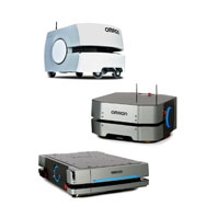
Designed to automate material transport tasks in factories and indoor facilities.
Related Contents

- Features
- Lineup
- Specifications
- Dimensions
- Catalog / Manual / CAD / Software
last update: September 1, 2025
LD Series
LD-60, LD-90, LD-90x, LD-60 ESD, LD-90 ESD, and LD-90x ESD
| Item | LD-60 | LD-90 | LD-90x | |
|---|---|---|---|---|
| Weight (with Battery) | 62 kg | |||
| Environment | Ambient temperature | 5 to 40°C | ||
| Ambient humidity | 5 to 95% (non-condensing) | |||
| Operating Environment | Indoor usage only, no excessive dust, no corrosive gas or liquid. Floor
must be free of water, oil, dirt, and debris. Direct sunlight may cause safety laser false positives. |
|||
| Dust / Smoke | Airborne particle size: > 37 μm
Floor accumulation: < 10 ml / m2 Avoid smoky areas |
|||
| Ingress Protection Class | IP20 | |||
| Altitude | 1000 m above mean sea level maximum | |||
| Floor
Conditions |
Minimum floor flatness | FF25 (ACI 117 standard) | ||
| Traversable step | 15 mm max. *1 | 10 mm max. *1 | ||
| Traversable gap | 15 mm max. *2 | |||
| Maximum Slope | Up to 60 kg: 4.8° / 8.3% incline
Over 60 kg: Level floor only |
|||
| Minimum floor
compressive strength |
2.6 Mpa. | 3.27 Mpa | ||
| Navigation | Routing | Autonomous routing by localizing with safety scanning laser based on
environment mapping |
||
| Environmental map
making method |
Scan by walking the AMR through the environment, and upload the
scan data to the MobilePlanner software |
|||
| Low Front Laser | One Class 1 laser at front of AMR with a 126° field of view | |||
| Side Laser (optional) | Two Class 1 lasers with a 270° field of view on the sides of payload
structure, user-mounted |
|||
| Visual Indicators | Light discs are located on the sides of the AMR. Additional indicators
can be added. |
|||
| Payload | Maximum Weight | 60 kg | 90 kg | |
| Mobility | Run Time (no payload) | 15 h approx. | 20 h approx. | |
| Run Time (full payload) | 12 h approx. | 15 h approx. | ||
| Maximum Speed | 1800 mm/s | 1350 mm/s | 900 mm/s | |
| Maximum Rotation Speed | 180 °/s | |||
| Stop Position
Repeatability (single AMR) *3 |
· To a position: ±65 mm
· To standard target: ±25 mm, ±2° · With CAPS: ±8 mm, ±0.5° · With HAPS: ±8 mm, ±0.4° |
|||
| Stop Position
Repeatability (Fleet) *3 |
· To a position: ±85 mm
· To standard target: ±35 mm, ±2° · With CAPS: ±12 mm, ±0.5° · With HAPS: ±10 mm, ±0.5° |
|||
| Drive wheels | Materials | Solid aluminum with non-marking, non-conductive, foam-filled rubber
tread |
||
| Passive casters | Materials | Conductive thermoplastic rubber on polyolefin | ||
| Auxiliary Power | 5 VDC±5%, 1 A switched Aux power
12 VDC±5%, 1 A switched Aux power 20 VDC±5%, 1 A switched Aux power 22 to 30 VDC (25.6 VDC nominal), 4 A switched 22 to 30 VDC (25.6 VDC nominal), 10 A switched 22 to 30 VDC (25.6 VDC nominal), 10 A safe, switched 10 A switched and 10 A safe switched are from the same source and pass through the same 10 A fuse, so the sum of their current must be less than 10 A. |
|||
| Standard | AMR | EN IS0 12100, EN ISO 13849-1, EN 60204-1, EN 1525, ANSI B56.5,
EN 61000-6-2, EN61000-6-4 |
||
| Battery | UN 38.3, UL 2271 | |||
| Docking Station | UL1012/CSA C22.2.107.2 | |||
| Wireless | IEEE 802.11 a/b/g | |||
| Cleanroom Rating | ISO 5 / Class 100 (AMR, Battery and Docking Station) | |||
| Safety
Features |
Safety Scanning Laser | One at front of AMR
Class 1 PLd safety per ISO13849-1 240° field of view |
||
| E-STOP Buttons | One on Operator Panel, additional E-STOP buttons can be added to
the payload structure |
|||
| Rear Sonar | Two at rear of AMR, 2 m range. Each pair includes one emitter and
one receiver working together. |
|||
| Front Bumper | Two pairs of sensors at the front of the AMR | |||
| Audible Indicators | Two speakers are included. Additional buzzers can be added. | |||
| Operator
Interface |
Display | 8.89 cm diagonal TFT, 320 x 240 pixels, color screen | ||
| Button | ON button, OFF button, Brake-release button, and keyed mode selection | |||
| User Interface | Wireless | 802.11 a/b/g | ||
| Ethernet | One general purpose, shielded, Auto-MDIX Ethernet port. | |||
| Serial | Two serial communication interfaces | |||
| Digital I/O | 16 inputs, 16 outputs | |||
| Audio | Digital audio in / out | |||
*1. A speed of 250 mm/s is recommended for traversing steps, and routine driving over steps should be avoided. Lower speeds may not traverse the step. Faster or frequent driving over steps will shorten the lifespan of the drivetrain components. All steps should have smooth, rounded profiles.
*2. AMR maximum speed is recommended for traversing gaps, and routine driving over gaps should be avoided. Lower speeds may not traverse the gap. Faster or frequent driving over gaps will shorten the lifespan of the drivetrain components.
*3. Stop position repeatability values were obtained using default AMR parameters and a map created by the LD-series AMR.
LD-250, LD-250 ESD Specifications
| Item | LD-250 | |
|---|---|---|
| Weight (with battery) | 148 kg | |
| Environment | Ambient temperature | 5 to 40°C |
| Ambient humidity | 5 to 95% (non-condensing) | |
| Operating Environment | Indoor usage only, no excessive dust, no corrosive gas or liquid. Floor
must be free of water, oil, dirt, and debris. Direct sunlight may cause safety laser false positives. |
|
| Dust / Smoke | Airborne particle size: > 37 μm
Floor accumulation: < 10 ml / m2 Avoid smoky areas |
|
| Ingress Protection Class | IP20 | |
| Altitude | 1000 m above mean sea level maximum | |
| Floor
Conditions |
Minimum floor flatness | FF25 (ACI 117 standard) |
| Traversable step | 10 mm max. *1 | |
| Traversable gap | 15 mm max. *2 | |
| Maximum Slope | Max. 1.7° / 3% incline | |
| Minimum floor
compressive strength |
5 Mpa | |
| Navigation | Routing | Autonomous routing by localizing with safety scanning laser based on
environment mapping |
| Environmental map
making method |
Scan by manually driving the AMR through the environment, and upload
the scan data to the MobilePlanner for map creation. |
|
| Low Front Laser | One Class 1 laser at front of AMR with a 126° field of view | |
| Side Laser (optional) | Two Class 1 lasers with a 270° field of view on the sides of payload
structure, user-mounted |
|
| Visual Indicators | Light discs are located on the sides of the AMR. Additional indicators
can be added. |
|
| Payload | Maximum Weight | 250 kg |
| Mobility | Run Time (no payload) | 13 h approx. |
| Run Time (full payload) | 10 h approx. | |
| Maximum Speed | 1200 mm/s | |
| Maximum Rotation Speed | 120 °/s | |
| Stop Position
Repeatability (single AMR) *3 |
· To a position: ±75 mm
· To standard target: ±25 mm, ±2° · With CAPS: ±8 mm, ±0.5° · With HAPS: ±8 mm, ±0.4° |
|
| Stop Position
Repeatability (Fleet) *3 |
· To a position: ±100 mm
· To standard target: ±35 mm, ±2° · With CAPS: ±14 mm, ±0.6° · With HAPS: ±10 mm, ±0.6° |
|
| Drive wheel | Materials | Aluminum with polyurethane tread |
| Passive caster | Materials | Elastomer (Polyurethane) |
| Auxiliary Power | 5 VDC±5%, 1 A switched Aux power
12 VDC±5%, 1 A switched Aux power 20 VDC±5%, 1 A switched Aux power 22 to 30 VDC (25.6 VDC nominal), 4 A switched 22 to 30 VDC (25.6 VDC nominal), 10 A switched 22 to 30 VDC (25.6 VDC nominal), 10 A safe, switched 10 A switched and 10 A safe switched are drawn from the same source, and pass through the same 10 A fuse, so the sum of their current must be less than 10 A. |
|
| Standards | AMR | EN IS0 12100, EN ISO 13849-1, EN 60204-1, EN 1525, ANSI B56.5,
EN 61000-6-2, EN 61000-6-4 |
| Battery | UN 38.3, UL 2271 | |
| Docking Station | UL1012/CSA C22.2.107.2 | |
| Wireless | IEEE 802.11 a/b/g | |
| Cleanroom Rating | ISO 5 / Class 100 (AMR, Battery and Docking Station) | |
| Safety
Features |
Safety Scanning Laser | One at front of AMR
Class 1 PLd safety per ISO13849-1 240° field of view |
| E-STOP Buttons | One at Operator Panel, one on each side. Additional E-STOP buttons
can be added to the payload structure |
|
| Rear Sensing | Time of flight (TOF) sensors | |
| Audible Indicators | Two speakers are included. Additional buzzers can be added | |
| Operator
Interface |
Display | 3.5 inch TFT, 320 x 240 pixels, color screen |
| Button | ON button, OFF button, Brake-release button, and keyed mode selection | |
| User Interface | Wireless | 802.11 a/b/g |
| Ethernet | One general purpose, shielded, Auto-MDIX Ethernet port. | |
| Serial | Two serial communication interfaces | |
| Digital I/O | 16 inputs, 16 outputs | |
| Audio | Digital audio in / out | |
*1. A speed of 600 mm/s is recommended for traversing steps, and routine driving over steps should be avoided. Lower speeds may not traverse the step. Faster or frequent driving over steps and gaps will shorten the lifespan of the drivetrain components. All steps should have smooth, rounded profiles.
*2. AMR maximum speed is recommended for traversing gaps, and routine driving over gaps should be avoided. Lower speeds may not traverse the gap. Faster or frequent driving over gaps will shorten the lifespan of the drivetrain components.
*3. Stop position repeatability values were obtained using default AMR parameters and a map created by the LD-series AMR.
Virtual Fleet Manager Software Minimum Hardware Requirements
| Fleet Size / AMR Count | Small / ≤ 5 | Medium ≤ 15 | Large ≤ 30 | X-Large ≤ 100 |
|---|---|---|---|---|
| Virtual CPU | 2 cores | 4 cores | ||
| Clockspeed | 4GHz | 8 GHz | 12 GHz | 16 GHz |
| Virtual RAM | 8 GB | 16 GB | 24 GB | 32 GB |
| Virtual Disk | 512 GB | 1 TB | ||
| FLOW software version | Minimum FLOW Core 4.0 | |||
Note: The PC/IPC/Server is supplied by the user.
High Accuracy Positioning System (HAPS)
| Sensor | Depth | 30 mm |
|---|---|---|
| Width | 160 mm | |
| Ingress Protection Class | IP64 | |
| Environment | -40 to 85°C | |
| LEDs | Power, tape present, left marker, right marker | |
| Magnetic Tape | Width | 25 mm |
| Orientation | South up | |
| Markers
(Magnetic Tape) |
Width | 25 mm |
| Length | 300 mm min. for 500 mm/s drive speed | |
| Orientation | North up | |
| Separation From Tape | 15 to 30 mm | |
| Connections | Front Sensor | RS232-1 (/dev/ttyUSB9) on the core |
| Rear Sensor | RS232-2 (/dev/ttyUSB10) on the core | |
| Power, Both Sensors | Aux power using the included splitter cable | |
| Stop Position Repeatability,
LD-60, LD-90 * |
Single AMR | ±8 mm position, 0.4° rotation |
| Fleet | ±10 mm position, 0.5° rotation | |
| Stop Position Repeatability,
LD-250 * |
Single AMR | ±8 mm position, 0.4° rotation |
| Fleet | ±10 mm position, 0.6° rotation |
* Stop position repeatability values were obtained using default AMR parameters and a map created by the LD-series AMR.
Cell Alignment Positioning System (CAPS)
| Stop Position Repeatability,
LD-60, LD-90, LD-90x * |
Single AMR | ±8 mm position, 0.5° rotation |
|---|---|---|
| Fleet | ±12 mm position, 0.5° rotation | |
| Stop Position Repeatability,
LD-250 * |
Single AMR | ±8 mm position, 0.5° rotation |
| Fleet | ±14 mm position, 0.6° rotation | |
| Type | Software license | |
* Stop position repeatability values were obtained using default AMR parameters and a map created by the LD-series AMR.
Battery
| Type | Lithium-Ion (LiFePO4) |
|---|---|
| Weight | 19 kg |
| Voltage | 22 to 30 VDC (25.6 VDC nominal) |
| Capacity | 72 Ah (battery cell nominal) |
| Recharge Time | 2 hrs. 10 min. for 20% to 80% charge |
| Ingress Protection Class | IP20 |
| Recharge Cycles | Approximately 2000 cycles * |
| Charging Method | Automatic or manual |
* Approximately 80% of nominal battery capacity will be available after using the battery at 100% depth of discharge at temperatures between 15°C to 35°C.
Docking Station
| Current | 8 A * |
|---|---|
| Power | 100 to 240 VAC, 50 to 60 Hz |
| Power Consumption | 800 W |
| Humidity | 5 to 95%, non-condensing |
| Temperature | 5 to 40°C |
| Dimensions (W × D × H) | 349 × 369 × 315 mm
495 × 495.5 × 317 mm (with floor plate) |
| Weight | 8.2 kg |
| Mounting | Wall bracket, directly to floor, or on floor with floor plate |
| Indicators | Power on: blue
Charging: yellow |
| Connector | For out-of-AMR battery charging |
* Circuit breaker built into AC power switch
Joystick (Pendant)
| Weight | 0.55 kg |
|---|---|
| IP Rating | IP56 |
Acuity Camera Specifications
| Field of View | 140° |
|---|---|
| Power Input | 12 VDC (±10%) supplied from AMR through power connector |
| Power Consumption | 3.3 W maximum |
MobilePlanner Software
| CPU | 1.5 GHz dual-core CPU recommended |
|---|---|
| Main Memory | 1.5 GB min. (4 GB min. recommended) |
| Hard Disk | At least 200 MB of available space |
| Video Memory | 256 MB min. |
| Display | XGA 1024 × 768, 16 million colors |
| Supported Languages | English, Japanese, German, French,
Italian, Korean, Spanish, Polish, Simplified Chinese, Traditional Chinese |
MD Series
| Item | Details | ||
|---|---|---|---|
| Model | MD-650 | MD-900 | |
| Weight (no battery or accessories) | 220 kg | ||
| Envi-
ronment |
Ambient Temperature | 5 to 40°C | |
| Storage Temperature | -20 to 60°C | ||
| Ambient Humidity | 5% to 95% (non-condensing) | ||
| Operating Environment | Indoor usage only, no corrosive or explosive gas or liquid | ||
| Dust / Smoke | Accumulated dust smaller than 37 μm cannot exceed 1.5 mL / m2 in the
operating environment. Avoid operating in areas with smoke. |
||
| Altitude | 2000 m maximum | ||
| Pollution Degree | 2 | ||
| Ingress Protection Class *1 | IP22 (IP10 for charging pads) | ||
| Enclosure Rating | Type 2 | ||
| Atmospheric | Non-hazardous environments (no explosive gas and oil mist). | ||
| Cleanroom Rating *2 | ISO 4 / Class 10 | ||
| Floor
Conditions |
Floor Requirements | No water, oil, or dirt | |
| Minimum Floor Flatness | FF25 (ACI 117 standard) | ||
| Minimum Floor Levelness | FL25 (ACI 117 standard) | ||
| Maximum Step Traversal
(speed limited *3) |
10 mm / 15 mm | ||
| Maximum Gap Traversal *4 | 20 mm / 30 mm | ||
| Maximum Slope | Max. 5° / 8.75% incline | ||
| Minimum Floor
Compressive Strength |
7.2 MPa | 9.4 MPa | |
| Minimum Coefficient of
Friction |
Flat surfaces: 0,6; Inclined surfaces: 0.8 | ||
| Navigation | Routing | Autonomous routing by localizing with Safety Laser Scanners, based on
environment mapping. |
|
| Environmental Map-
Making Method |
Scan by driving the AMR through the environment and uploading the scan
data to the MobilePlanner. |
||
| Low Lasers | Two Low Lasers are provided to detect obstacles below the scanning plane
of the Safety Laser Scanners. |
||
| Supplementary Laser
Scanners (Optional) |
Two optional, Supplementary Laser Scanners can be added for object
detection in the vertical plane |
||
| Visual Indicators | Light discs are located on the sides of the AMR. Light strips are located on
the front and back of the AMR. Additional indicators can be added. |
||
| Maximum Payload Capacity | 650 kg | 900 kg | |
| Mobility | Run Time *5 | 10 h (no payload); 8 h (full payload) | |
| Swing Radius | 729 mm | ||
| Turn Radius | 0 mm | ||
| Maximum Translational
Speed (forward and reverse) |
2200 mm/s | 1800 mm/s | |
| Maximum Translational
Acceleration |
900 mm/s2 | ||
| Maximum Translational
Deceleration |
1300 mm/s2 | ||
| Maximum Rotational
Speed *6 |
60 °/s | ||
| Maximum Rotational
Acceleration |
100 °/s2 | ||
| Maximum Rotational
Deceleration |
150 °/s2 | ||
| Maximum Moment of
Inertia |
250 kg-m2 | 300 kg-m2 | |
| Stop Position Repeatability
(Single AMR) *7 |
To a position: ±55 mm, ±2°
To standard target: ±25 mm, ±2° With HAPS: ±8 mm, ±0.5° With CAPS: ±4 mm, ±0.4° |
||
| Stop Position Repeatability
(Fleet) *7 |
To a position: ±75 mm, ±2°
To standard target: ±35 mm, ±2° With HAPS: ±10 mm, ±0.5° With CAPS: ±16 mm, ±0.5° |
||
| Drive
Wheels |
Materials | Steel wheels with ESD tread | |
| Passive
Casters |
Materials | Cast iron wheels with polyurethane tread | |
| Auxiliary
Power |
Unregulated | 40 to 57 VDC (51.2 VDC nominal); 40 A fused | |
| Regulated | 23 to 25 VDC; 0.7 A fused | ||
| Standards | AMR | EN ISO 12100, EN ISO 13849-1, EN 60204-1, EN ISO 10218-1,
EN 61326-3-1, EN 61326-1, EN 12895, EN ISO 3691-4, CAN/UL 3100, CAN/CSA-Z434, KS C 9610-6-2, KS C 9610-6-4, ANSI RIA 15.08 |
|
| Battery | ANSI/CAN/UL/ULC 2271, UN 38.3 | ||
| Charging Station | EN 61204-7, EN 62477-1, UL1012, CAN/CSA C22.2.107.2 | ||
| Wireless | IEEE 802.11 a/b/g | ||
| Certification
Markings |
Battery | cTUVus, CE | |
| Power Supply Box and
Docking Target |
cTUVus | ||
| Signal
Interfaces |
Wireless | Fleet communication and other maintenance functions | |
| RJ-45 Ports | Four ports for connections to internal devices | ||
| Digital I/O | Eight PNP / sourcing inputs; Eight PNP / sourcing outputs | ||
| Safety | Emergency stop and protective signals, alternate safety zone switching, and
no-motion output |
||
| Lights | Connects user-supplied visual signal devices | ||
| Buzzer | Connects user-supplied audible signal devices | ||
| Safety
Features |
Safety Laser Scanners | Two Safety Laser Scanners are included to provide a 360° detection area
around the AMR. The scanning plane is positioned 175 mm above the floor. Lasers are rated as Class 1M, eye-safe, per IEC 60825-1 and 21 CFR 1040.10 and 1040.11. |
|
| Safety Laser Scanner
Zone Sets |
A pair of safety-rated alternate safety zone inputs can toggle the Safety Laser
Scanner zones between a default configuration or an alternate configuration. |
||
| E-STOP Buttons | Five E-STOP buttons are located on the AMR (sides and Operator Panel).
Additional E-STOP buttons can be added to the payload structure. |
||
| Audible Indicators | Two speakers are included. Additional buzzers can be added. | ||
| Emergency Stop | Stops the AMR and requires user intervention to resume operation. | ||
| Protective Stop | Stops the AMR temporarily and automatically resumes operation when
safety conditions are met. |
||
| Operator
Panel |
Display | 127 mm diagonal LCD | |
| Controls | • E-STOP button
• ON/OFF buttons • Brake release button • Pendant port • Keyed Mode Selection Switch |
||
*1. The supplied Top Plate Plugs must be inserted to achieve an IP22 rating.
*2. Cleanroom ratings are associated with the AMR and charging components when used together as a complete system.
*3. Traversing a 10 mm step must occur at speeds below 500 mm/s in the forward direction and 400 mm/s in the reverse direction. Traversing a 15 mm step must occur at speeds below 300 mm/s in the forward and reverse directions. Frequent driving over steps will shorten the lifespan of the drivetrain components. Steps should have smooth, rounded profiles.
*4. 20 mm gaps may be traversed at any speed. Traversing a 30 mm gap must occur at speeds below 2000 mm/s for MD-650 and speeds below 1500 mm/s for MD-900. Frequent driving over gaps will shorten the lifespan of the drivetrain components.
*5. Auxiliary power draw will impact these times.
*6. The maximum rotational speed is reduced to 45 degrees/s when the AMR is traveling at speeds over 100 mm/s.
*7. Stop position repeatability values were obtained using default AMR parameters and a map created by the MD-series AMR.
MobilePlanner Software Requirements
| MobilePlanner, PC | Operating System | Windows 10 (64-bit version), Windows 11 |
|---|---|---|
| CPU | 1.5 GHz dual-core CPU recommended | |
| Main Memory | 1.5 GB min. (4 GB min. recommended) | |
| Hard Disk | At least 200 MB of available space | |
| Video Memory | 256 MB min. | |
| Display | XGA 1280 x 720, 16 million colors minimum | |
| MobilePlanner,
Tablet Edition |
Operating System | Android® OS, Version 9 or newer, minimum 2 GB of RAM |
| iOS®, Version 10 or newer | ||
| Supported Languages | English, German, Japanese, French, Italian, Korean, Spanish, Polish,
Simplified Chinese and Traditional Chinese. |
|
Virtual Fleet Manager Software Minimum Hardware Requirements
| Fleet Size / AMR Count | Small / ≤ 5 | Medium ≤ 15 | Large ≤ 30 | X-Large > 30 *1 |
|---|---|---|---|---|
| Virtual CPU | 2 cores | 4 cores | ||
| Clockspeed | 4GHz | 8 GHz | 12 GHz | 16 GHz |
| Virtual RAM | 8 GB | 16 GB | 24 GB | 32 GB |
| Virtual Disk | 512 GB | 1 TB | ||
| FLOW software version | Minimum FLOW Core 4.0 | |||
*1. Contact your local OMRON representative for fleets larger than 100.
Note: The PC/IPC/Server is supplied by the user.
Charging Station
| Maximum Current | Input current: 25 A
Output current: 120 A (nominal) *1 |
|---|---|
| Input Voltage | 3-phase
200 to 240 VAC, 50/60 Hz (Delta/Wye) 380 to 415 VAC, 50/60 Hz (Wye only) |
| Output voltage | 40 to 57 VDC |
| Power Consumption | 7.75 kW |
| Maximum Power Output | 6.84 kW |
| Humidity | 5% to 95%, non-condensing |
| Ambient Operating Temperature | 5 to 40°C |
| Storage Temperature | -20 to 60°C |
| Ingress Protection | IP20 (IP10 for charging pads) |
| Cleanroom Rating *2 | ISO 4 / Class 10 |
| Altitude | 2000 m maximum |
| Pollution degree | 2 |
| Equipment Class | 1 |
| Weight | Power Supply Box: 111 kg
Docking Target: 28 kg |
| Docking Target Mounting | To floor and/or wall |
*1. Fused at 150 A
*2. Cleanroom ratings are associated with the AMR and charging components when used together as a complete system.
High Accuracy Positioning System
| Ingress Protection | IP64 | |
|---|---|---|
| Environment | -40 to 85°C | |
| Magnetic Tape | Width | 25 mm |
| Orientation | South up | |
| Markers
(Magnetic Tape) |
Width | 25 mm |
| Length | 250 mm min. for 500 mm/s drive speed | |
| Orientation | North up | |
| Separation from Tape | 20 to 30 mm | |
| Protective Covering Tape (recommended) | Mighty Line Safety Floor Tape, Solid (102 mm width) | |
Pendant
| Ambient Operating Temperature | 0 to 40°C |
|---|---|
| Storage Temperature | -20 to 65°C |
| Humidity | 5% to 95%, non-condensing |
| Altitude | 2000 m |
| Ingress Protection Class | IP30 |
Battery
| Type | Lithium-Ion (LiFePO4) |
|---|---|
| Voltage | 40 to 57 VDC (51.2 VDC nominal) |
| Capacity | 38 Ah nominal |
| Energy | 2048 Wh nominal |
| Recharge Time | 19.6 minutes (from 20% to 80%) *1 |
| Charge Cycles | Approximately 3000 cycles *2 *3 |
| Charging Method | Automatic or manual |
| Ambient Operating Temperature | 5 to 40°C |
| Storage Temperature | < 1 month: -20 to 45°C
< 3 months: -20 to 35°C > 3 months: 20 to 25°C |
| Humidity (Storage) | 65% or less |
| Humidity (Operation) | 5% to 95%, non-condensing |
| Altitude | 4500 m, operating
15240 m, transporting |
| Ingress Protection Class | IP33 |
| Weight | 29 kg |
*1. Charging time can vary based on battery cell temperature and state of charge.
*2. Approximately 80% of nominal battery capacity will be available after using the battery at 100% depth of discharge.
*3. Under manufacturer's test conditions of 25°C ±3°, 25% to 85% relative humidity, 40 A charge/discharge, 57 and 40 VDC charge/discharge, with 60 minutes of inactivity after charging/discharging. Actual cycles may vary according to the application.
HD-1500
| Item | Details | |
|---|---|---|
| Weight (with Battery) | 506 kg | |
| Environment | Ambient Temperature | 5 to 40°C |
| Storage Temperature | -20 to 60°C | |
| Ambient Humidity | 5% to 95% (non-condensing) | |
| Operating Environment | Indoor usage only, no corrosive or explosive gas or liquid, no
ionizing radiation |
|
| Altitude | 2000 m maximum | |
| Ingress Protection Class | IP20 | |
| Dust / Smoke | Accumulated dust smaller than 37 μm cannot exceed 1.5 mL / m2
in the operating environment. Avoid operating in areas with smoke. |
|
| Enclosure Rating | Type 1 | |
| Cleanroom Rating *1 | ISO 5 / Class 100 | |
| Floor
Conditions |
Floor Requirements | No water, oil or dirt |
| Minimum Floor Flatness | FF25 (ACI 117 standard) | |
| Traversable Step *2 | 10 mm max. | |
| Traversable Gap | 20 mm max. | |
| Maximum Slope | 5° / 8.75% incline | |
| Minimum Floor
Compressive Strength |
5 MPa | |
| Minimum Coefficient of
Friction |
0.6 | |
| Navigation | Routing | Autonomous routing by localizing with safety scanning laser,
based on environment mapping |
| Environmental
Map-Making Method |
Scan by driving the AMR through the environment and upload
the scan data to MobilePlanner |
|
| Low Lasers | Two Low Lasers are provided to detect obstacles below the
scanning plane of the Safety Laser Scanners |
|
| Supplementary Laser
Scanners (optional) |
Two optional, Supplementary Laser Scanners can be added
for object detection in the vertical plane |
|
| Visual Indicators | Light discs are located on the sides of the AMR. Light strips are
located on the front and back of the AMR. Additional indicators can be added. |
|
| Maximum Payload Capacity | 1500 kg | |
| Mobility | Run Time *3 | 12.5 h (no payload), 9 h (full payload) |
| Maximum Translational
Speed (forward and reverse) |
1800 mm/s | |
| Maximum Rotational Speed *4 | 60°/s | |
| Swing Radius | 982 mm | |
| Turn Radius | 0 mm | |
| Maximum Translational
Acceleration |
900 mm/s2 | |
| Maximum Rotational
acceleration/deceleration |
150°/s2 | |
| Maximum Moment of Inertia | 490 kg-m2 | |
| Stop Position Repeatability
(Single AMR) *5 |
To a position: ±70 mm, ±2°
To standard target: ±25 mm, ±2° With HAPS: ±8 mm, ±0.4° With CAPS: ±5 mm, ±0.4° |
|
| Stop Position Repeatability
(Fleet) *5 |
To a position: ±75 mm, ±2°
To standard target: ±35 mm, ±2° With HAPS: ±10 mm, ±0.75° With CAPS: ±16 mm, ±0.5° |
|
| Drive Wheels | Materials | Non-marking, static dissipative polyurethane on steel rim |
| Passive Casters | Materials | Non-marking polyurethane on cast iron rim |
| Auxiliary Power | Unregulated | 48 to 57 VDC (52.8 nominal); 50 A fused |
| Regulated | 23 to 25 VDC; two channels fused at 1.6 A | |
| Standard | AMR | EN ISO 12100, EN ISO 13849-1, EN 60204-1, EN ISO 10218-1,
EN 61326-3-1, EN 61326-1, EN ISO 3691-4, EN 12895, CAN/CSA Z434, CAN / UL 3100, KS C 9610-6-2, KS C 9610-6-4 |
| Battery | ANSI/CAN/UL/ULC 2271, UN 38.3 | |
| Charging Station | UL 1012, CAN/CSA C22.2.107.2, EN 61204-7, EN 62477-1 | |
| Wireless | IEEE 802.11 a/b/g | |
| Certification
Markings |
AMR | cTUVus |
| Battery | cURus, CE | |
| Power Supply Box | cTUVus | |
| Docking Target | cTUVus | |
| Signal
Interfaces |
Wireless | Two integrated wireless antennas |
| Ethernet Port | One RJ-45 port included for maintenance and access to
the internally mounted NX102 unit. |
|
| Digital I/O | Eight PNP (sourcing) inputs
Eight PNP (sourcing) outputs |
|
| Analog I/O | Four -10 to 10 VDC analog inputs
Four -10 to 10 VDC analog outputs |
|
| Audio | Digital audio out | |
| Safety
Features |
Scanning Safety Lasers | Two Safety Scanning Lasers are included to provide a 360°
detection area around the AMR. The scanning plane is positioned 181 mm above the floor. Lasers are rated as Class 1M, eye-safe, per IEC 60825-1, 21 CFR 1040.10 and 1040.11. |
| Safety Laser Scanner
Zone Sets |
A pair of safety-rated alternate safety zone inputs can toggle the
Safety Laser Scanner zones between a default configuration or an alternate configuration. |
|
| E-Stop Buttons | Five E-STOP buttons are located on the AMR (sides and Operator
Panel). Additional E-STOP buttons can be added to the payload structure. |
|
| Audible Indicators | Two speakers are included. Additional buzzers can be added. | |
| Emergency Stop Interface | Dual-channel emergency stop inputs and outputs | |
| Safety Outputs | Dual-channel safety outputs | |
| Protective Stop Interface | Dual-channel protective stop inputs | |
| Operator
Panel |
Display | 178 mm diagonal LCD |
| Controls | • E-STOP button
• ON/OFF buttons • Brake release button • Pendant port • Maintenance port • Main disconnect switch |
|
*1. Cleanroom ratings are associated with the AMR and charging components when used together as a complete system.
*2. A speed of 500 mm/s in the forward direction and 400 mm/s in the reverse direction is recommended for traversing steps. Routine driving over steps should be avoided. Lower speeds may not traverse the step. Faster or frequent driving over steps and gaps will shorten the lifespan of the drivetrain components. All steps should have smooth, rounded profiles.
*3. Auxiliary power draw will impact these times.
*4. The maximum rotational speed is reduced to 45°/s when the AMR is traveling at speeds over 300 mm/s.
*5. Stop position repeatability values were obtained using default AMR parameters and a map created by the HD-1500 AMR.
MobilePlanner Software Requirements
| MobilePlanner, PC | Operating System | Windows 10 (64-bit version), Windows 11 |
|---|---|---|
| CPU | 1.5 GHz dual-core CPU recommended | |
| Main Memory | 1.5 GB min. (4 GB min. recommended) | |
| Hard Disk | At least 400 MB of available space | |
| Video Memory | 256 MB min. | |
| Display | XGA 1280 x 720, 16 million colors minimum | |
| MobilePlanner,
Tablet Edition |
Operating System | Android® OS, Version 9 or newer,
minimum 2 GB of RAM |
| iOS®, Version 10 or newer | ||
| Supported Languages | English, German, Japanese, French,
Italian, Korean, Spanish, Simplified Chinese and Traditional Chinese. |
|
Virtual Fleet Manager Software Minimum Hardware Requirements
| Fleet Size / AMR Count | Small / ≤ 5 | Medium ≤ 15 | Large ≤ 30 | X-Large > 30 *1 |
|---|---|---|---|---|
| Virtual CPU | 2 cores | 4 cores | ||
| Clockspeed | 4 GHz | 8 GHz | 12 GHZ | 16 GHz |
| Virtual RAM | 8 GB | 16 GB | 24 GB | 32 GB |
| Virtual Disk | 512 GB | 1 TB | ||
| FLOW Software Version | Minimum FLOW Core 4.0 | |||
*1. Contact your local OMRON representative for fleets larger than 100.
Note: The PC/IPC/Server is supplied by the user.
Charging Station
| Maximum Current | Input current: 25 A
Output current: 120 A (nominal) *1 |
|---|---|
| Input Voltage | 3-phase
200 to 240 VAC, 50/60 Hz (Delta/Wye) 380 to 415 VAC, 50/60 Hz (Wye only) |
| Output Voltage | 40 to 57 VDC |
| Power Consumption | 7.75 kW |
| Maximum Power Output | 6.84 kW |
| Humidity | 5% to 95%, non-condensing |
| Ambient Operating Temperature | 5 to 40°C |
| Storage Temperature | -20 to 60°C |
| Ingress Protection | IP20 (IP10 for charging pads) |
| Cleanroom Rating *2 | ISO 5 / Class 100 |
| Pollution Degree | 2 |
| Equipment Class | 1 |
| Weight | Power Supply Box: 108 kg
Docking Target: 27 kg |
| Docking Target Mounting | To floor and/or wall |
*1. Fused at 150 A
*2. Cleanroom ratings are associated with the AMR and charging components when used together as a complete system.
High Accuracy Positioning System
| Ingress Protection | IP64 | |
|---|---|---|
| Environment | -40 to 85°C | |
| Magnetic Tape | Width | 25 mm |
| Orientation | South up | |
| Markers
(Magnetic Tape) |
Width | 25 mm |
| Length | 300 mm min. for 500 mm/s drive speed | |
| Orientation | North up | |
| Separation from Tape | 20 to 30 mm | |
| Protective Covering Tape
(recommended) |
Mighty Line Safety Floor Tape, Solid
(102 mm width) |
|
Pendant
| Ambient Operating Temperature | 0 to 40°C |
|---|---|
| Storage Temperature | -20 to 65°C |
| Humidity | 5% to 95%, non-condensing |
| Altitude | 2000 m |
| Ingress Protection Class | IP30 |
Battery
| Type | Lithium-Ion (LiFePO4) |
|---|---|
| Voltage | 48 to 57 VDC (52.8 nominal) |
| Capacity | 68 Ah nominal |
| Recharge Time | 24 min. (20% to 80% charge) |
| Charge Cycles | Approximately 8000 cycles *1 |
| Charging Method | Automatic or manual |
| Ambient Operating Temperature | 5 to 40°C |
| Storage Temperature | -20 to 60°C (less than 2 weeks)
-20 to 35°C (more than 2 weeks) |
| Humidity | 5% to 95%, non-condensing |
| Altitude | 4500 m, operating
15240 m, transporting |
| Ingress Protection Class | IP20 |
| Weight | 69 kg |
*1. Approximately 80% of nominal battery capacity will be available after using the battery at 100% depth of discharge, at a temperatures of 23°C.
last update: September 1, 2025