G70D-SOC16 / FOM16
Relay Terminal
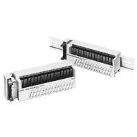
Compact, Low-profile 16-point Output terminal
Related Contents
- Features
- Lineup
- Specifications
- Dimensions
- Catalog / Manual / CAD / Software
last update: July 1, 2021
Ratings
Relay Specifications (G6D Relay)
The following specifications apply to G6D Relays mounted in a G70D Relay Terminal and not the G6D Relay itself.
Coil Ratings (per G6D Relay)
| Rated voltage | 24 V DC |
|---|---|
| Rated current | 10.5 mA |
| Coil resistance | 2,880 Ω |
| Must-operate voltage | 70% max. of rated voltage |
| Must release voltage | 10% min. of rated voltage |
| Max. voltage | 130% of rated voltage |
| Power consumption | Approx. 200 mW |
Note: 1. The must-operate voltage is 75% or less of the rated voltage if the relay is mounted upside down.
2. Rated current and coil resistance were measured at a coil temperature of 23° C with a tolerance of ±10%.
3. Operating characteristics were measured at a coil temperature of 23° C.
4. The maximum allowable voltage is the maximum value of the allowable voltage range for the relay coil operating
power supply. There is no continuous allowance.
5. The rated current includes the terminal’s LED current.
Contact Ratings (per G6D Relay *1)
| Load | Resistive load (cosφ = 1) | |
|---|---|---|
| Rated load | 3 A at 250 V AC, 3 A at 30 V DC | |
| Rated carry current | 3 A | |
| Max. switching voltage | 250 V AC, 30 V DC | |
| Max. switching current | 3 A | |
| Min. permissible load (reference value) *2 | 10 mA at 5 V DC | |
| Endurance | Electrical | 100,000 operations min.
(under and at the rated load at 1,800 operations/hr) |
| Mechanical | 20,000,000 operations min. (at 18,000 operations/hr) | |
*1. Up to 3 A can be carried by the power supply terminals for outputs (terminals B0 to B7.)
*2. This value is for a switching frequency of 120 times per minute.
Power MOSFET Relay Specifications (G3DZ Power MOSFET Relay)
Note: The following specifications apply to G3DZ Power MOSFET relays mounted in a G70D Relay terminal and not the G3.
Input (per G3DZ Power MOSFET Relay)
| Rated voltage | 24 V DC | |
|---|---|---|
| Operating voltage | 19.2 to 28.8 V DC | |
| Voltage level | Must-operate | 19.2 V DC max. |
| Must release | 1 V DC min. | |
| Input impedance | 4 kΩ±20% | |
| Rated current | 8.2 mA±20% | |
Note: The rated current includes the terminal’s LED current.
Output (per G3DZ Power MOSFET Relay)
| Load voltage | 3 to 264 V AC, 3 to 125 V DC |
|---|---|
| Load current | 100 μA to 0.3 A |
| Inrush current | 6 A (10 ms) |
Characteristics
| Item | G70D-SOC16(-1) | G70D-FOM16 |
|---|---|---|
| Classification | Relay outputs | Power MOSFET relay outputs |
| Contact configuration | 16 points (SPST-NO × 16) | |
| Contact structure | Single | --- |
| Contact material | Ag-Alloy (Cd free) | --- |
| Contact resistance | 100 mΩ max. *1 | --- |
| Must-operate time | 10 ms max. *2 | 6 ms max. |
| Release time | 10 ms max. *2 | |
| Isolation method | --- | Photocoupler |
| Output ON-resistance | --- | 2.4 Ω max. |
| Open-state leakage current | --- | 10 μA max. (at 125 V DC) |
| Max. switching frequency | Mechanical: 18,000 operations/h
Rated load: 1,800 operations/h |
--- |
| Insulation resistance | 100 MΩ min. (at 500 V DC) | |
| Dielectric strength | 2,000 V AC for 1 min between coil and
contact |
2,000 V AC for 1 min between input and
output terminals |
| Noise immunity | Power input (normal mode): 600 V for 10 min with a pulse width of 100 ns to 1 μs
Power input (common mode): 1.5 kV for 10 min with a pulse width of 100 ns to 1 μs Input cable (coiling): 1.5 kV for 10 min with a pulse width of 100 ns to 1 μs Unit body (coiling): 600 V for 10 min with a pulse width of 100 ns to 1 μs |
|
| Vibration resistance | Destruction: 10 to 55 to 10 Hz, 0.5-mm amplitude (1.0-mm double)
Malfunction: 10 to 55 to 10 Hz, 0.375-mm amplitude (0.75-mm double) |
|
| Shock resistance | Destruction: 300 m/s2
Malfunction: 100 m/s2 |
|
| Operating voltage range | 24 V DC +10%/-15% | |
| Current consumption | Approx. 300 mA at 24 V DC *3 | Approx. 300 mA at 24 V DC *4 |
| Cable length | Between block and controller: 5 m max. (reference value for AWG28)
Between block and external device: Dependent on load |
|
| LED color | Operation indicator: orange; power supply: green | |
| Coil surge absorber | Diode (400 V, 300 mA) | |
| Ambient temperature | Operating: 0 to 55°C (with no icing or condensation)
Storage: -20 to 65°C (with no icing or condensation) |
|
| Ambient humidity | Operating: 35% to 85% | |
| Mounting strength | No damage when 49 N pull load was applied for 1 s in all directions (except for 9.8 N in
direction of rail) |
|
| Terminal strength | Tightening torque: 0.78 to 0.98 N·m
Pull strength: 49 N for 1 min |
|
| Weight | Approx. 200 g | |
Note: These values are initial values.
*1. Measurement: 1 A at 5 V DC
*2. Ambient temperature: 23°C
*3. Current consumption is when all points are ON and includes G6D Relay coil current but does not include any external
load current.
*4. Current consumption is when all points are ON and includes G3DZ input current but does not include any external load
current.
last update: July 1, 2021